View all ArmorStart Distributed Motor Controllers
提供多种维修方式
提供多种维修方式
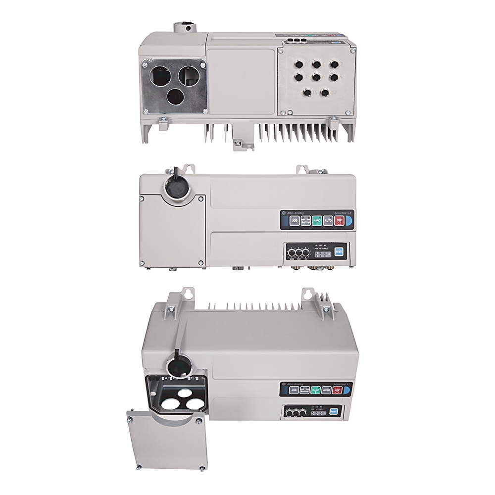
294E-FD4P2Z-G1-3
变频器
Serial #:
This product has not been verified. Please register your product to confirm authenticity.
生命周期状态:
活跃
产品概览
生命周期状态:
活跃
产品概览
技术规格
Construction
Mechanical
Environmental
Electrical
图纸
文档
认证
配件
替代产品
技术说明
| 宽度 |
381mm
|
|---|---|
| 高度 |
219.32mm
|
| 深度 |
202.27mm
|
| 极数 |
电源电路:3
|
| 线规 |
源端制动器:每个端子 #16~AWG (1.0~4.0mm²)
|
| 防护等级 (IP) |
IP66
|
|---|---|
| 运输重量,约 |
7.3kg
|
| 额定功率 |
源制动:10A@600V AC
|
| 冲击 |
Opsal:30G,超过IEC 60947-1
|
| 密封板选项 |
电源和电机导管入口(无电缆)
|
| 电线剥皮长度 |
0.35±0.01″(9±2mm)
|
| 振动 |
抗冲击性:2.5G @ 测试符合 MIL-STD-810G,超过 IEC 60947-1
|
| 紧固扭矩 |
源制动扭矩:4.8(2)in-lb (0.5(0.2)Nm)
|
| 机械寿命操作 |
断开连接:200000
|
| 断开锁定 |
最大直径为3/8″(9.5mm)的锁扣或搭扣
|
| 线缆类型 |
多股铜线
|
| 断开LOTO锁 |
最多支持2个锁或搭扣
|
| 海拔高度 |
1000m
|
|---|---|
| 存储和运输温度 |
−25°C
|
| 传导发射 |
EN 61800-3,C3
|
| 湿度 |
5~95% 无凝露
|
| 浪涌瞬态 |
1kV (12) L-L,2kV (2) L-N(接地)
|
| 辐射发射 |
EN 61800-3,C3
|
| 射频电磁场 |
EN 55011 2类组,10V/m,80MHz~1GHz
|
| 防护等级(NEMA) |
4
|
| 污染等级 |
3
|
| 射频传导干扰抗扰度 |
10V @ 150kHz...80MHz
|
| 静电放电 |
4kV接触放电和8kV空气放电
|
| 快速脉冲 |
2kV(电源)、2kV(PE)、1kV(通信和控制)
|
| 工作温度 |
−20~40°C (−4~104°F),在分支电路中安装额定值正确的线路电抗器时,最高可达50°C (122°F)且无降额
|
| DHCP超时 |
30″
|
|---|---|
| Web服务器 |
HTTP 1.1
|
| 输入ON状态电流(引脚4) |
2.6mA@24V DC
|
| 工作介电强度 |
2000V AC,符合IEC
|
| 过电压类别 |
电源电路:III
|
| 熔断器额定值 |
UL 级熔断器(最大45A)
|
| 消费实例(命令) |
默认值为4个单词(实例 154)
|
| 生成实例(状态) |
默认值为16个字(实例 156)
|
| 绝缘电压 (Ui) |
输出额定值:根据IEC标准,额定为2000V AC
|
| 无故障电源穿越 |
电源电路:10ms
|
| 额定输入工作电压 |
24V DC
|
| 输入关断状态电流 |
<1.5mA
|
| 输入关断状态电压 |
5V DC
|
| 工作频率 |
电源电路:50/60Hz (±10%)
|
| 用户选项 1 |
HAND-OFF-AUTO 选择键盘
|
| 额定工作输入电流,最大 |
电源电路:6.5A@400V AC,50Hz,2.0Hp(1.5kW)
|
| 脱扣额定值 |
电源电路:200%硬件限制,300%瞬时故障
|
| 短路协调 |
类型 1
|
| 过载类型 |
功率电路:150% @ 60″ 或 200% @ 3″ @ 固态 I²t
|
| 绝缘电压 |
额定值250V AC
|
| Carrier frequency:载波频率 |
电源电路:2~10kHz,变频器额定值基于4kHz
|
| 速度调节-开环带滑差补偿 |
功率电路:在40∶1的速度范围内,基本速度的±2%
|
| 介电耐受性 |
电源电路:2500V AC,符合IEC
|
| 并发TCP连接数 |
网络连接:TCP 和 UDP 上最多5个封装消息
|
| RMS 对称安培 |
5kA @ 480Y/277(短路电流额定值)
|
| 电源 |
控制电路(外部电源):6.6W@开关和非开关电源要求
|
| 电流,标称值 |
控制电路(外部电源):275mA@开关和非开关电源要求
|
| 峰值浪涌 |
控制电路(外部电源):<5A,持续35ms @ 非开关电源要求
|
| 电压 |
控制电路(外部电源):19.2–26.4V DC@非开关电源要求
|
| 行程类别 |
电源电路:Class 10保护,具有速度敏感响应和下电过载保持功能
|
| 最大电流 |
控制电路(外部电源):450mA@非开关电源要求
|
| 最大功率 |
控制电路(外部电源):6.6W +(24V DC×用户自定义)@开关电源和非开关电源要求
|
| 过电压 |
电源电路:380~480V AC输入 − 在810V直流母线电压时跳闸(相当于575V AC进线)
|
| 欠压 |
电源电路:380~480V AC输入 - 在390V直流母线电压时跳闸(相当于275V AC进线)
|
| 停止模式 |
电源电路:多种可编程停止模式,包括 rA、惯性停止、DC制动、rA至保持和S曲线
|
| 数据 |
通过 TCP 和 UDP 进行传输
|
| 加速/减速 |
电源电路:两个独立可编程的加速和减速时间。每个时间都可以在0~600s范围内以0.1s的增量进行编程。
|
| 允许在工业区应用 |
Yes
|
| 最大输出频率 |
400Hz
|
| 支持 EtherNet/IP协议 |
Yes
|
| 电源频率 |
50/60Hz
|
| 最大输入设备数量 |
6
|
| 输出OFF状态漏电流,最大值 |
1µA
|
| 最大输出数量 |
6
|
| 输入滤波 |
100µs
|
| 最大插座数 |
150
|
| 输出电源电压(开关电源) |
A1/A2
|
| 每个连接的输入 |
1/每个
|
| 每个连接的输出 |
1/每个
|
| 最大输出阻断电压 |
35V DC
|
| 传感器输入漏电流,最大 |
<2.5mA
|
| 输出类型 |
直流拉出型
|
| 传感器输入工作电压 |
19.2...26V DC
|
| 并发会话 |
Web服务器:20
|
| 额定输出工作电压(Ue) |
19.2…26.4V DC
|
| 输出工作电流 (Ie),标称 |
每点500mA
|
| 最大输出热电流 (Ithe) |
每点500mA
|
| 输出状态 |
常开(NO)
|
| 额定脉冲电压(Uimp) |
电源电路:4kV
|
| 输出应用类型 |
符合IEC DC-1、DC-13
|
| 以太网端口 |
2(嵌入式交换机)
|
| 消息支持 |
单播或多播
|
| 输入导通状态电压(引脚4),标称值 |
10…26.4V DC @ 24V DC
|
| IP配置 |
静态、DHCP或BOOTP
|
| 输入电源电压 |
未切换电源 A3/A2
|
| 输入类型 |
24V DC 电流灌入
|
| 最大并发显式报文数(CIP Class 3) |
网络连接:6
|
| 输入电源端子 |
电源电路:L1、L2、L3
|
| 电机电源端子 |
电源电路:T1、T2、T3
|
| 应用 |
电源电路:三相
|
| 支持的以太网网络拓扑 |
星型、树型、线性和环型
|
| 效率 |
电源电路:典型值为97.5%
|
| DeviceLogix 输入/输出响应 |
输入额定值:500Hz时为2ms
|
| 输出负载类型 |
阻性或轻度感性
|
| PE(接地)端子 |
电源电路:4个PE端子
|
| 复位模式 |
电源电路:自动/手动
|
| 输入弹跳滤波器(软件可配置) |
OFF-ON或ON-OFF:0.5ms+64ms
|
| 以太网通信速率 |
10/100 Mbps,半双工或全双工
|
| 1类连接API |
网络连接:2–3200ms
|
| 输入连接类型 |
单键M12,快速断开
|
| 输出连接类型 |
单键M12,快速断开
|
| 以太网电缆 |
5e类:屏蔽或非屏蔽
|
| 3类连接API |
网络连接:100–10000ms
|
| 输出频率 |
电源电路:0~400Hz,可编程
|
| 源制动(EM制动)电流 |
电源电路:最大负载电流为3A
|
| 安全性 |
Web服务器:登录名和密码可配置
|
| 电机控制类型 |
电源电路:滑差补偿(V/Hz)
|
| 电源 |
控制电路(外部电源):NEC 2 类
|
| 额定工作电压,最大 |
电源电路:400Y/230…480Y/277(−15%,+10%)
|
| 设备级环路支持 |
信标性能,IEEE 1588透明时钟
|
| 以太网连接器 |
M12,D 编码,母头,带以太网匹配功能,4针
|
| 请求包间隔 (RPI) |
网络连接:默认20ms(最小2ms)
|
| 额定工作电压 |
控制电路(外部电源):24V DC(+10 %,−20 %)
|
| 网页功能 |
Web 服务器:状态、诊断和配置选项卡
|
| 输出过流保护 |
1.5A(所有输出的总和不得超过该值)
|
| 电子邮件 |
Web 服务器:支持简单邮件传输协议(SMTP)
|
| 输出浪涌抑制 |
集成二极管,有助于防止切换负载时的损坏
|
| EtherNet/IP ODVA – 一致性测试 |
EtherNet/IP 互操作性性能 - 按照 A9 PF 2.1
|
| 地址冲突检测(ACD) |
EtherNet/IP 设备的 IPv4 地址冲突检测
|
| 过压保护 |
控制电路(外部电源):反极性保护
|
| 传感器拉电流输入(引脚1),最大值 |
每点50mA(为一台设备供电时总计最大300mA)
|
| 控制穿越 |
电源电路:最小跨越时间为0.5 s,典型值为2 s
|
| 电机控制功能 |
电源电路:飞速启动、V/F比率、母线调节器、4个预设速度
|
| 数据包速率 (pps) |
500个数据包/秒 (2000µs),Tx,500个数据包/秒 (2000µs),Rx
|
| 输出电流(每个) |
控制电路(外部电源):500mA@开关电源要求
|
| 输入电流(每个) |
控制电路(外部电源):50mA@非开关电源要求
|
| 电机电缆长度,最大 |
电源电路:10m (32′)(CE应用),电源电路:14m (45.9′)(非CE应用)
|
| 输入数量(×50mA) |
控制电路(外部电源):用户自定义 @ 切换和非切换电源要求
|
| 输出数量(×500mA) |
控制电路(外部电源):用户自定义 @ 切换和非切换电源要求
|
| IPS 选项 |
控制电路(内部电源):内部50W电源为输入、输出和逻辑控制提供24V DC(需要400Y/230V~480Y/277V@50/60Hz的三相线路电源)
|
| 最大输入/输出连接数(CIP 1类) |
网络连接:支持最多2个1类CIP连接[独占所有者(数据)或仅接听]。每个PLC一个连接。仅接听连接需要建立数据连接。
|
| 基本信息 | 出版 |
|---|---|
| 电路保护装置和 SCCR 表 | -- |
| 产品简介 | -- |
| 技术规格 | -- |
| 接线图 | -- |
| 技术数据 | 出版 |
|---|---|
| 290-td001_-zh-p | 290-TD001 |
| 用户手册 | 出版 |
|---|---|
| 290e-um001_-zh-p | 290E-UM001 |
| 选型指南 | 出版 |
|---|---|
| 280-sg002_-zh-p | 280-SG002 |
- 澳大利亚RCM
- CE
截至 2026-03-14,此产品已获得上述多项认证。此日期前后销售的产品,所获认证可能有所不同。请查阅产品标签,确认具体产品所持有的相关认证。
每页项目:
每页项目:
| 技术说明 |
|---|
技术规格
| 宽度 |
381mm
|
|---|---|
| 高度 |
219.32mm
|
| 深度 |
202.27mm
|
| 极数 |
电源电路:3
|
| 线规 |
源端制动器:每个端子 #16~AWG (1.0~4.0mm²)
|
| 防护等级 (IP) |
IP66
|
|---|---|
| 运输重量,约 |
7.3kg
|
| 额定功率 |
源制动:10A@600V AC
|
| 冲击 |
Opsal:30G,超过IEC 60947-1
|
| 密封板选项 |
电源和电机导管入口(无电缆)
|
| 电线剥皮长度 |
0.35±0.01″(9±2mm)
|
| 振动 |
抗冲击性:2.5G @ 测试符合 MIL-STD-810G,超过 IEC 60947-1
|
| 紧固扭矩 |
源制动扭矩:4.8(2)in-lb (0.5(0.2)Nm)
|
| 机械寿命操作 |
断开连接:200000
|
| 断开锁定 |
最大直径为3/8″(9.5mm)的锁扣或搭扣
|
| 线缆类型 |
多股铜线
|
| 断开LOTO锁 |
最多支持2个锁或搭扣
|
| 海拔高度 |
1000m
|
|---|---|
| 存储和运输温度 |
−25°C
|
| 传导发射 |
EN 61800-3,C3
|
| 湿度 |
5~95% 无凝露
|
| 浪涌瞬态 |
1kV (12) L-L,2kV (2) L-N(接地)
|
| 辐射发射 |
EN 61800-3,C3
|
| 射频电磁场 |
EN 55011 2类组,10V/m,80MHz~1GHz
|
| 防护等级(NEMA) |
4
|
| 污染等级 |
3
|
| 射频传导干扰抗扰度 |
10V @ 150kHz...80MHz
|
| 静电放电 |
4kV接触放电和8kV空气放电
|
| 快速脉冲 |
2kV(电源)、2kV(PE)、1kV(通信和控制)
|
| 工作温度 |
−20~40°C (−4~104°F),在分支电路中安装额定值正确的线路电抗器时,最高可达50°C (122°F)且无降额
|
| DHCP超时 |
30″
|
|---|---|
| Web服务器 |
HTTP 1.1
|
| 输入ON状态电流(引脚4) |
2.6mA@24V DC
|
| 工作介电强度 |
2000V AC,符合IEC
|
| 过电压类别 |
电源电路:III
|
| 熔断器额定值 |
UL 级熔断器(最大45A)
|
| 消费实例(命令) |
默认值为4个单词(实例 154)
|
| 生成实例(状态) |
默认值为16个字(实例 156)
|
| 绝缘电压 (Ui) |
输出额定值:根据IEC标准,额定为2000V AC
|
| 无故障电源穿越 |
电源电路:10ms
|
| 额定输入工作电压 |
24V DC
|
| 输入关断状态电流 |
<1.5mA
|
| 输入关断状态电压 |
5V DC
|
| 工作频率 |
电源电路:50/60Hz (±10%)
|
| 用户选项 1 |
HAND-OFF-AUTO 选择键盘
|
| 额定工作输入电流,最大 |
电源电路:6.5A@400V AC,50Hz,2.0Hp(1.5kW)
|
| 脱扣额定值 |
电源电路:200%硬件限制,300%瞬时故障
|
| 短路协调 |
类型 1
|
| 过载类型 |
功率电路:150% @ 60″ 或 200% @ 3″ @ 固态 I²t
|
| 绝缘电压 |
额定值250V AC
|
| Carrier frequency:载波频率 |
电源电路:2~10kHz,变频器额定值基于4kHz
|
| 速度调节-开环带滑差补偿 |
功率电路:在40∶1的速度范围内,基本速度的±2%
|
| 介电耐受性 |
电源电路:2500V AC,符合IEC
|
| 并发TCP连接数 |
网络连接:TCP 和 UDP 上最多5个封装消息
|
| RMS 对称安培 |
5kA @ 480Y/277(短路电流额定值)
|
| 电源 |
控制电路(外部电源):6.6W@开关和非开关电源要求
|
| 电流,标称值 |
控制电路(外部电源):275mA@开关和非开关电源要求
|
| 峰值浪涌 |
控制电路(外部电源):<5A,持续35ms @ 非开关电源要求
|
| 电压 |
控制电路(外部电源):19.2–26.4V DC@非开关电源要求
|
| 行程类别 |
电源电路:Class 10保护,具有速度敏感响应和下电过载保持功能
|
| 最大电流 |
控制电路(外部电源):450mA@非开关电源要求
|
| 最大功率 |
控制电路(外部电源):6.6W +(24V DC×用户自定义)@开关电源和非开关电源要求
|
| 过电压 |
电源电路:380~480V AC输入 − 在810V直流母线电压时跳闸(相当于575V AC进线)
|
| 欠压 |
电源电路:380~480V AC输入 - 在390V直流母线电压时跳闸(相当于275V AC进线)
|
| 停止模式 |
电源电路:多种可编程停止模式,包括 rA、惯性停止、DC制动、rA至保持和S曲线
|
| 数据 |
通过 TCP 和 UDP 进行传输
|
| 加速/减速 |
电源电路:两个独立可编程的加速和减速时间。每个时间都可以在0~600s范围内以0.1s的增量进行编程。
|
| 允许在工业区应用 |
Yes
|
| 最大输出频率 |
400Hz
|
| 支持 EtherNet/IP协议 |
Yes
|
| 电源频率 |
50/60Hz
|
| 最大输入设备数量 |
6
|
| 输出OFF状态漏电流,最大值 |
1µA
|
| 最大输出数量 |
6
|
| 输入滤波 |
100µs
|
| 最大插座数 |
150
|
| 输出电源电压(开关电源) |
A1/A2
|
| 每个连接的输入 |
1/每个
|
| 每个连接的输出 |
1/每个
|
| 最大输出阻断电压 |
35V DC
|
| 传感器输入漏电流,最大 |
<2.5mA
|
| 输出类型 |
直流拉出型
|
| 传感器输入工作电压 |
19.2...26V DC
|
| 并发会话 |
Web服务器:20
|
| 额定输出工作电压(Ue) |
19.2…26.4V DC
|
| 输出工作电流 (Ie),标称 |
每点500mA
|
| 最大输出热电流 (Ithe) |
每点500mA
|
| 输出状态 |
常开(NO)
|
| 额定脉冲电压(Uimp) |
电源电路:4kV
|
| 输出应用类型 |
符合IEC DC-1、DC-13
|
| 以太网端口 |
2(嵌入式交换机)
|
| 消息支持 |
单播或多播
|
| 输入导通状态电压(引脚4),标称值 |
10…26.4V DC @ 24V DC
|
| IP配置 |
静态、DHCP或BOOTP
|
| 输入电源电压 |
未切换电源 A3/A2
|
| 输入类型 |
24V DC 电流灌入
|
| 最大并发显式报文数(CIP Class 3) |
网络连接:6
|
| 输入电源端子 |
电源电路:L1、L2、L3
|
| 电机电源端子 |
电源电路:T1、T2、T3
|
| 应用 |
电源电路:三相
|
| 支持的以太网网络拓扑 |
星型、树型、线性和环型
|
| 效率 |
电源电路:典型值为97.5%
|
| DeviceLogix 输入/输出响应 |
输入额定值:500Hz时为2ms
|
| 输出负载类型 |
阻性或轻度感性
|
| PE(接地)端子 |
电源电路:4个PE端子
|
| 复位模式 |
电源电路:自动/手动
|
| 输入弹跳滤波器(软件可配置) |
OFF-ON或ON-OFF:0.5ms+64ms
|
| 以太网通信速率 |
10/100 Mbps,半双工或全双工
|
| 1类连接API |
网络连接:2–3200ms
|
| 输入连接类型 |
单键M12,快速断开
|
| 输出连接类型 |
单键M12,快速断开
|
| 以太网电缆 |
5e类:屏蔽或非屏蔽
|
| 3类连接API |
网络连接:100–10000ms
|
| 输出频率 |
电源电路:0~400Hz,可编程
|
| 源制动(EM制动)电流 |
电源电路:最大负载电流为3A
|
| 安全性 |
Web服务器:登录名和密码可配置
|
| 电机控制类型 |
电源电路:滑差补偿(V/Hz)
|
| 电源 |
控制电路(外部电源):NEC 2 类
|
| 额定工作电压,最大 |
电源电路:400Y/230…480Y/277(−15%,+10%)
|
| 设备级环路支持 |
信标性能,IEEE 1588透明时钟
|
| 以太网连接器 |
M12,D 编码,母头,带以太网匹配功能,4针
|
| 请求包间隔 (RPI) |
网络连接:默认20ms(最小2ms)
|
| 额定工作电压 |
控制电路(外部电源):24V DC(+10 %,−20 %)
|
| 网页功能 |
Web 服务器:状态、诊断和配置选项卡
|
| 输出过流保护 |
1.5A(所有输出的总和不得超过该值)
|
| 电子邮件 |
Web 服务器:支持简单邮件传输协议(SMTP)
|
| 输出浪涌抑制 |
集成二极管,有助于防止切换负载时的损坏
|
| EtherNet/IP ODVA – 一致性测试 |
EtherNet/IP 互操作性性能 - 按照 A9 PF 2.1
|
| 地址冲突检测(ACD) |
EtherNet/IP 设备的 IPv4 地址冲突检测
|
| 过压保护 |
控制电路(外部电源):反极性保护
|
| 传感器拉电流输入(引脚1),最大值 |
每点50mA(为一台设备供电时总计最大300mA)
|
| 控制穿越 |
电源电路:最小跨越时间为0.5 s,典型值为2 s
|
| 电机控制功能 |
电源电路:飞速启动、V/F比率、母线调节器、4个预设速度
|
| 数据包速率 (pps) |
500个数据包/秒 (2000µs),Tx,500个数据包/秒 (2000µs),Rx
|
| 输出电流(每个) |
控制电路(外部电源):500mA@开关电源要求
|
| 输入电流(每个) |
控制电路(外部电源):50mA@非开关电源要求
|
| 电机电缆长度,最大 |
电源电路:10m (32′)(CE应用),电源电路:14m (45.9′)(非CE应用)
|
| 输入数量(×50mA) |
控制电路(外部电源):用户自定义 @ 切换和非切换电源要求
|
| 输出数量(×500mA) |
控制电路(外部电源):用户自定义 @ 切换和非切换电源要求
|
| IPS 选项 |
控制电路(内部电源):内部50W电源为输入、输出和逻辑控制提供24V DC(需要400Y/230V~480Y/277V@50/60Hz的三相线路电源)
|
| 最大输入/输出连接数(CIP 1类) |
网络连接:支持最多2个1类CIP连接[独占所有者(数据)或仅接听]。每个PLC一个连接。仅接听连接需要建立数据连接。
|
图纸
文档
|
电路保护装置和 SCCR 表
基本信息
-- |
|
产品简介
基本信息
-- |
|
技术规格
基本信息
-- |
|
接线图
基本信息
-- |
|
290-td001_-zh-p
技术数据
290-TD001 |
|
290e-um001_-zh-p
用户手册
290E-UM001 |
|
280-sg002_-zh-p
选型指南
280-SG002 |
| 基本信息 | 出版 |
|---|---|
| 电路保护装置和 SCCR 表 | -- |
| 产品简介 | -- |
| 技术规格 | -- |
| 接线图 | -- |
| 技术数据 | 出版 |
| 290-td001_-zh-p | 290-TD001 |
| 用户手册 | 出版 |
| 290e-um001_-zh-p | 290E-UM001 |
| 选型指南 | 出版 |
| 280-sg002_-zh-p | 280-SG002 |
认证
- 澳大利亚RCM
- CE
截至 2026-03-14,此产品已获得上述多项认证。此日期前后销售的产品,所获认证可能有所不同。请查阅产品标签,确认具体产品所持有的相关认证。
配件
每页项目:
替代产品
每页项目:
技术说明
| 技术说明 |
|---|
变频器
294E-FD4P2Z-G1-3
关闭
打印
Copyright ©2026 Rockwell Automation, Inc.