| Communications | DeviceNet |
|---|---|
| Option 1 | FWD REV HOA Selector Keypad |
| Width | 260 mm |
|---|---|
| Height | 217.83 mm |
| Depth | 166.5 mm |
| Number of poles | Power circuit: 3 |
| Wire size | Power terminal: (2) #18... AWG (0.8...5.2 mm²) per terminal |
| Degree of protection (IP) | IP66 |
|---|---|
| Shipping weight, approx | 4.6 kg |
| Power rating | Power terminal: 25A @ 600V AC |
| Shock | Opsal: 30 G, exceeds IEC 60947-1 |
| Gland plate options | Gland kits |
| Wire strip length | 0.35 ±0.01 in (9 ±2 mm) |
| Vibration | Opsal: 2.5 G @ tested to MIL-STD-810G, exceeds IEC 60947-1 |
| Tightening torque | Power terminal: 10.6 ±2 in-lb (1.2 ±0.2 Nm) |
| Mechanical life operations | Disconnect: 200000 |
| Disconnect lock out | Maximum of 3/8 in (9.5 mm) diam lock shackle or hasp |
| Contactor opening delay | 8 ms |
| Contactor closing delay | 18 ms |
| Wire type | Multi-strand copper wire |
| Disconnect LOTO locks | Up to 2 locks or hasps are supported |
| Contactor utilization category | AC-1, AC-3, AC-4 per IEC (refer to life load curves) |
| Baud rates | 500 kbps |
|---|---|
| Communication | DeviceNet |
| Web server | HTTP 1.1 |
| Input ON-state current (pin 4) | 2.6mA @ 24V DC |
| DeviceNet input current surge | 500 mA @ peak inrush |
| Operating dielectric withstand | 2000V AC per IEC |
| DeviceNet input current | 50mA @ 24V DC |
| Overvoltage category | Power circuit: III |
| Product type | Full voltage reversing starter |
| Fuse rating | UL Class fuse (45 A, maximum) |
| DeviceNet supply voltage rating | Range 11...25V DC @ 24V DC nominal |
| Insulation voltage (Ui) | Output ratings: rated 2000V AC per IEC |
| Rated operating current, max | Power circuit: 0.24...3.5A @ 2Hp (1.5 kW) |
| Rated input operation voltage | 24V DC |
| Input OFF-state current | <1.5 mA |
| Input OFF-state voltage | 5V DC |
| Distance, max | 500 m (1630 ft) @ 125 Kbps |
| Operating frequency | Power circuit: 50/60 Hz (±10%) |
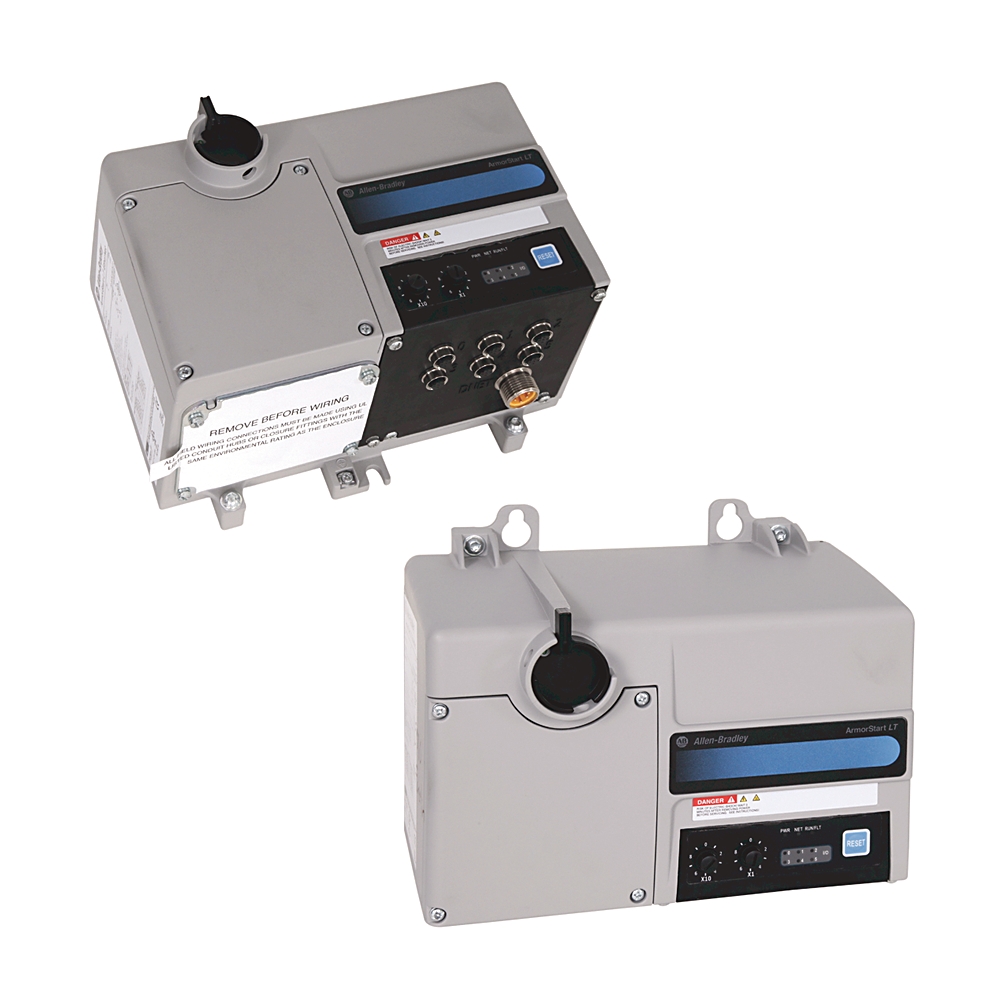
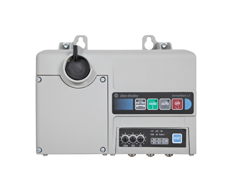
| User options 1 | HAND-OFF-AUTO selector keypad with FORWARD and REVERSE |
| Trip rating | Power circuit: 120% of full load current (FLC) setting |
| Application in industrial area permitted (SCPD list) | Size per NFPA 70 (NEC) or NFPA 79 for group motor applications |
| Short circuit coordination | Type 1 |
| Overload type | Power circuit: solid-state I²t |
| Insulation voltage | Rated 250V AC |
| Dielectric withstand | Power circuit: 2500V AC per IEC |
| Concurrent TCP connections | Network connections: maximum of 15 encapsulated messages over both TCP and UDP |
| RMS symmetrical amperes | 5 kA @ 480Y/277 (short circuit current rating) |
| Power | Control circuit (external source): 6.6 W @ switched and unswitched power supply requirements |
| Current, nom | Control circuit (external source): 275 mA @ switched and unswitched power supply requirements |
| Peak inrush | Control circuit (external source): <5 A for 35 ms @ unswitched power supply requirements |
| Voltage | Control circuit (external source): 19.2...26.4V DC @ unswitched power supply requirements |
| Trip class | Power circuit: Class 10 (default), 15, 20 with thermal memory retention (see motor overload trip curves) |
| Current, max | Control circuit (external source): 450 mA @ unswitched power supply requirements |
| Power, max | Control circuit (external source): 6.6 W + (24V DC x user defined) @ switched and unswitched power supply requirements |
| Supporting protocol for DeviceNet | True |
| Application in industrial area permitted | True |
| Mains frequency | 50/60 Hz |
| Number of input devices, max | 6 |
| Output OFF-state leakage current, max | 1 µa |
| Number of outputs, max | 6 |
| Number of configurable digital I/O | 6 |
| Input filtering | 100 µs |
| OFF time, min | 200 ms |
| Auto-baud rate identification | True |
| Group 2 - slave only device type | True |
| Polled I/O messaging | True |
| Change of state messaging | True |
| Cyclic messaging | True |
| Explicit messaging | True |
| Full parameter object support | True |
| Group 4 - off-line node recovery messaging | True |
| Configuring consistency value | True |
| Unconnected messaging manager (UCMN) | True |
| Output supply voltage (switched power) | A1/A2 |
| Input per connection | 1/each |
| Output per connection | 1/each |
| Output blocking voltage, max | 35V DC |
| Sensor input leakage current, max | <2.5 mA |
| Type of outputs | DC sourcing |
| Sensor input operating voltage | 19.2...26V DC |
| Concurrent sessions | Web server: 20 |
| Rated output operating voltage (Ue) | 19.2...26.4V DC |
| Disconnect | Motor disconnect |
| Output operating current (Ie), nom | 500 mA per point |
| Output thermal current (Ithe), max | 500 mA per point |
| Connection type | Quick disconnects |
| Output state | Normally open (NO) |
| Rated impulse voltage (Uimp) | Power circuit: 4 kV |
| Output utilization category | DC-1, DC-13 per IEC |
| Input ON-state voltage (pin 4), nom | 10...26.4V DC @ 24V DC |
| Input supply voltage | Unswitched power A3/A2 |
| Type of inputs | 24V DC current sinking |
| Concurrent explicit messages, max (CIP Class 3) | Network connections: 6 |
| Input power terminals | Power circuit: L1, L2, L3 |
| Motor power terminals | Power circuit: T1, T2, T3 |
| Application | Power circuit: three-phase |
| Overload reset level | Power circuit: 1...100% TCU |
| DeviceLogix I/O response | Input ratings: 2 ms @ 500 Hz |
| Output load types | Resistive or light inductive |
| PE (earth ground) terminal | Power circuit: 4 PE terminals |
| Reset mode | Power circuit: automatic/manual |
| Input bounce filter (software configurable) | OFF-ON or ON-OFF: 0.5 ms + 64 ms |
| Class 1 connection API | Network connections: 2...3200 ms |
| Input connection type | Single keyed M12, quick disconnect |
| Output connection type | Single keyed M12, quick disconnect |
| Class 3 connection API | Network connections: 100...10000 ms |
| Security | Web server: login and password configurable |
| Power supply | Control circuit (external source): NEC class 2 |
| Rated operating voltage, max | Power circuit: 400Y/230...480Y/277 (-15%, +10%) |
| Request packet interval (RPI) | Network connections: 20 ms default (2 ms minimum) |
| Rated operating voltage | Control circuit (external source): 24V DC (+10%, -20%) |
| Webpage features | Web server: status, diagnostics and configuration tabs |
| Output overcurrent protection | 1.5 A (the sum of all outputs cannot exceed this value) |
| Web server: support simple mail transfer protocol (SMTP) | |
| Output surge suppression | Integrated diode to help protect against switching loads |
| Overvoltage protection | Control circuit (external source): reverse-polarity protected |
| Sensor sourcing input current (pin 1), max | 50 mA per point (maximum 300 mA total for sourcing one device) |
| Output current (each) | Control circuit (external source): 500 mA @ switched power supply requirements |
| Input current (each) | Control circuit (external source): 50 mA @ unswitched power supply requirements |
| Number of inputs (x 50 mA) | Control circuit (external source): user defined @ switched and unswitched power supply requirements |
| Number of outputs (x 500 mA) | Control circuit (external source): user defined @ switched and unswitched power supply requirements |
| I/O connections, max (CIP Class 1) | Network connections: supports up to 2 class 1 CIP connections [exclusive owner (data) or listen-only]. One connection per PLC. Listen only connection requires a data connection to be established. |
| Altitude | 2000 m |
|---|---|
| Operating temperature | -20 °C |
| Storage and transportation temperature | -25 °C |
| Conducted emission | EN 60947-4-1, Class A |
| Humidity | 5...95% (noncondensing) |
| Surge transient | 1 kV (12) L-L, 2 kV (2) L-N (earth) |
| Radiated emissions | EN 60947-4-1, Class A |
| Radio frequency electromagnetic field | EN 60947-4-1, 10V/m, 80 MHz...1 GHz, 10V/m, 1.4 GHz...2 GHz |
| Degree of protection (NEMA) | 4 |
| Pollution degree | 3 |
| Radio frequency conducted disturbance immunity | 10V @ 150kHz...80 MHz |
| Electrostatic discharge | 4 kV contact and 8 kV air |
| Fast transient | 2 kV (power), 2 kV (PE), 1 kV (communications and control) |
| 图纸 | |
|---|---|
| Dimension Drawings (PDF) | Download (PDF) |
| 2D Drawings (DXF/DWG) | Download (ZIP) |
| 图纸 |
|---|
| Dimension Drawings (PDF) Download (PDF) |
| 2D Drawings (DXF/DWG) Download (ZIP) |
| 类型 | 资源 | 出版 |
|---|---|---|
| General | Product Cutsheet | -- |
| General | Wiring Diagrams | -- |
| General | Specifications | -- |
技术规格
| Communications | DeviceNet |
|---|---|
| Option 1 | FWD REV HOA Selector Keypad |
| Width | 260 mm |
|---|---|
| Height | 217.83 mm |
| Depth | 166.5 mm |
| Number of poles | Power circuit: 3 |
| Wire size | Power terminal: (2) #18... AWG (0.8...5.2 mm²) per terminal |
| Degree of protection (IP) | IP66 |
|---|---|
| Shipping weight, approx | 4.6 kg |
| Power rating | Power terminal: 25A @ 600V AC |
| Shock | Opsal: 30 G, exceeds IEC 60947-1 |
| Gland plate options | Gland kits |
| Wire strip length | 0.35 ±0.01 in (9 ±2 mm) |
| Vibration | Opsal: 2.5 G @ tested to MIL-STD-810G, exceeds IEC 60947-1 |
| Tightening torque | Power terminal: 10.6 ±2 in-lb (1.2 ±0.2 Nm) |
| Mechanical life operations | Disconnect: 200000 |
| Disconnect lock out | Maximum of 3/8 in (9.5 mm) diam lock shackle or hasp |
| Contactor opening delay | 8 ms |
| Contactor closing delay | 18 ms |
| Wire type | Multi-strand copper wire |
| Disconnect LOTO locks | Up to 2 locks or hasps are supported |
| Contactor utilization category | AC-1, AC-3, AC-4 per IEC (refer to life load curves) |
| Baud rates | 500 kbps |
|---|---|
| Communication | DeviceNet |
| Web server | HTTP 1.1 |
| Input ON-state current (pin 4) | 2.6mA @ 24V DC |
| DeviceNet input current surge | 500 mA @ peak inrush |
| Operating dielectric withstand | 2000V AC per IEC |
| DeviceNet input current | 50mA @ 24V DC |
| Overvoltage category | Power circuit: III |
| Product type | Full voltage reversing starter |
| Fuse rating | UL Class fuse (45 A, maximum) |
| DeviceNet supply voltage rating | Range 11...25V DC @ 24V DC nominal |
| Insulation voltage (Ui) | Output ratings: rated 2000V AC per IEC |
| Rated operating current, max | Power circuit: 0.24...3.5A @ 2Hp (1.5 kW) |
| Rated input operation voltage | 24V DC |
| Input OFF-state current | <1.5 mA |
| Input OFF-state voltage | 5V DC |
| Distance, max | 500 m (1630 ft) @ 125 Kbps |
| Operating frequency | Power circuit: 50/60 Hz (±10%) |
| User options 1 | HAND-OFF-AUTO selector keypad with FORWARD and REVERSE |
| Trip rating | Power circuit: 120% of full load current (FLC) setting |
| Application in industrial area permitted (SCPD list) | Size per NFPA 70 (NEC) or NFPA 79 for group motor applications |
| Short circuit coordination | Type 1 |
| Overload type | Power circuit: solid-state I²t |
| Insulation voltage | Rated 250V AC |
| Dielectric withstand | Power circuit: 2500V AC per IEC |
| Concurrent TCP connections | Network connections: maximum of 15 encapsulated messages over both TCP and UDP |
| RMS symmetrical amperes | 5 kA @ 480Y/277 (short circuit current rating) |
| Power | Control circuit (external source): 6.6 W @ switched and unswitched power supply requirements |
| Current, nom | Control circuit (external source): 275 mA @ switched and unswitched power supply requirements |
| Peak inrush | Control circuit (external source): <5 A for 35 ms @ unswitched power supply requirements |
| Voltage | Control circuit (external source): 19.2...26.4V DC @ unswitched power supply requirements |
| Trip class | Power circuit: Class 10 (default), 15, 20 with thermal memory retention (see motor overload trip curves) |
| Current, max | Control circuit (external source): 450 mA @ unswitched power supply requirements |
| Power, max | Control circuit (external source): 6.6 W + (24V DC x user defined) @ switched and unswitched power supply requirements |
| Supporting protocol for DeviceNet | True |
| Application in industrial area permitted | True |
| Mains frequency | 50/60 Hz |
| Number of input devices, max | 6 |
| Output OFF-state leakage current, max | 1 µa |
| Number of outputs, max | 6 |
| Number of configurable digital I/O | 6 |
| Input filtering | 100 µs |
| OFF time, min | 200 ms |
| Auto-baud rate identification | True |
| Group 2 - slave only device type | True |
| Polled I/O messaging | True |
| Change of state messaging | True |
| Cyclic messaging | True |
| Explicit messaging | True |
| Full parameter object support | True |
| Group 4 - off-line node recovery messaging | True |
| Configuring consistency value | True |
| Unconnected messaging manager (UCMN) | True |
| Output supply voltage (switched power) | A1/A2 |
| Input per connection | 1/each |
| Output per connection | 1/each |
| Output blocking voltage, max | 35V DC |
| Sensor input leakage current, max | <2.5 mA |
| Type of outputs | DC sourcing |
| Sensor input operating voltage | 19.2...26V DC |
| Concurrent sessions | Web server: 20 |
| Rated output operating voltage (Ue) | 19.2...26.4V DC |
| Disconnect | Motor disconnect |
| Output operating current (Ie), nom | 500 mA per point |
| Output thermal current (Ithe), max | 500 mA per point |
| Connection type | Quick disconnects |
| Output state | Normally open (NO) |
| Rated impulse voltage (Uimp) | Power circuit: 4 kV |
| Output utilization category | DC-1, DC-13 per IEC |
| Input ON-state voltage (pin 4), nom | 10...26.4V DC @ 24V DC |
| Input supply voltage | Unswitched power A3/A2 |
| Type of inputs | 24V DC current sinking |
| Concurrent explicit messages, max (CIP Class 3) | Network connections: 6 |
| Input power terminals | Power circuit: L1, L2, L3 |
| Motor power terminals | Power circuit: T1, T2, T3 |
| Application | Power circuit: three-phase |
| Overload reset level | Power circuit: 1...100% TCU |
| DeviceLogix I/O response | Input ratings: 2 ms @ 500 Hz |
| Output load types | Resistive or light inductive |
| PE (earth ground) terminal | Power circuit: 4 PE terminals |
| Reset mode | Power circuit: automatic/manual |
| Input bounce filter (software configurable) | OFF-ON or ON-OFF: 0.5 ms + 64 ms |
| Class 1 connection API | Network connections: 2...3200 ms |
| Input connection type | Single keyed M12, quick disconnect |
| Output connection type | Single keyed M12, quick disconnect |
| Class 3 connection API | Network connections: 100...10000 ms |
| Security | Web server: login and password configurable |
| Power supply | Control circuit (external source): NEC class 2 |
| Rated operating voltage, max | Power circuit: 400Y/230...480Y/277 (-15%, +10%) |
| Request packet interval (RPI) | Network connections: 20 ms default (2 ms minimum) |
| Rated operating voltage | Control circuit (external source): 24V DC (+10%, -20%) |
| Webpage features | Web server: status, diagnostics and configuration tabs |
| Output overcurrent protection | 1.5 A (the sum of all outputs cannot exceed this value) |
| Web server: support simple mail transfer protocol (SMTP) | |
| Output surge suppression | Integrated diode to help protect against switching loads |
| Overvoltage protection | Control circuit (external source): reverse-polarity protected |
| Sensor sourcing input current (pin 1), max | 50 mA per point (maximum 300 mA total for sourcing one device) |
| Output current (each) | Control circuit (external source): 500 mA @ switched power supply requirements |
| Input current (each) | Control circuit (external source): 50 mA @ unswitched power supply requirements |
| Number of inputs (x 50 mA) | Control circuit (external source): user defined @ switched and unswitched power supply requirements |
| Number of outputs (x 500 mA) | Control circuit (external source): user defined @ switched and unswitched power supply requirements |
| I/O connections, max (CIP Class 1) | Network connections: supports up to 2 class 1 CIP connections [exclusive owner (data) or listen-only]. One connection per PLC. Listen only connection requires a data connection to be established. |
| Altitude | 2000 m |
|---|---|
| Operating temperature | -20 °C |
| Storage and transportation temperature | -25 °C |
| Conducted emission | EN 60947-4-1, Class A |
| Humidity | 5...95% (noncondensing) |
| Surge transient | 1 kV (12) L-L, 2 kV (2) L-N (earth) |
| Radiated emissions | EN 60947-4-1, Class A |
| Radio frequency electromagnetic field | EN 60947-4-1, 10V/m, 80 MHz...1 GHz, 10V/m, 1.4 GHz...2 GHz |
| Degree of protection (NEMA) | 4 |
| Pollution degree | 3 |
| Radio frequency conducted disturbance immunity | 10V @ 150kHz...80 MHz |
| Electrostatic discharge | 4 kV contact and 8 kV air |
| Fast transient | 2 kV (power), 2 kV (PE), 1 kV (communications and control) |
图纸
| 图纸 | |
|---|---|
| Dimension Drawings (PDF) | Download (PDF) |
| 2D Drawings (DXF/DWG) | Download (ZIP) |
| 图纸 |
|---|
| Dimension Drawings (PDF) Download (PDF) |
| 2D Drawings (DXF/DWG) Download (ZIP) |
文档
|
Product Cutsheet
General
-- |
|
Wiring Diagrams
General
-- |
|
Specifications
General
-- |
| 类型 | 资源 | 出版 |
|---|---|---|
| General | Product Cutsheet | -- |
| General | Wiring Diagrams | -- |
| General | Specifications | -- |
配件
技术说明
Loading
Copyright ©2025 Rockwell Automation, Inc.