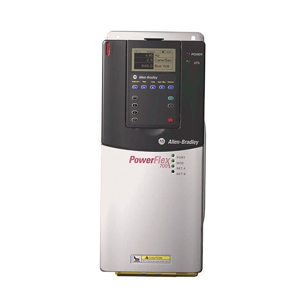
PowerFlex 700 AC Drive 8.7 A 4 kW 20B
Catalog #: 20BC8P7A0AYNADA0
Rockwell Automation announces that as of
November 30, 2023,
the PowerFlex 700 AC Drive 8.7 A 4 kW 20B will be discontinued and no longer available
for sale.
Customers are encouraged to remove references to the affected product(s).
Discontinued Date:
November 30, 2023
Replacement Category:
Engineering Replacement
Rockwell Automation announces that as of
November 30, 2023,
the PowerFlex 700 AC Drive 8.7 A 4 kW 20B will be discontinued and no longer available for
sale.
Customers are encouraged to remove references to the affected product(s).
Discontinued Date:
November 30, 2023
Replacement Category:
Engineering Replacement
| Brake IGBT | Brake IGBT Installed |
|---|---|
| Brake Resistor | No Internal |
| Feedback Options | No ftdback |
| Filter Options | W/ EMC Filt & ComModeChoke |
| Internal Communication Module | DeviceNet |
| Product Family | PowerFlex 700 AC Drive |
| Degree of protection (IP) | IP20 |
|---|---|
| Shock | 15 G peak for 11 ms duration (±1.0 ms) |
| PWM frequency | 4 kHz @ 540V DC |
| Vibration | 0.152 mm (0.006 in) displacement, 1 G peak |
| Number of analogue outputs | 2 |
|---|---|
| Mains voltage | 400 V |
| Integrated breaking resistance | False |
| Brake IGBT | Brake IGBT installed |
| Internal communication module | DeviceNet |
| Fuse current rating | 15A @ 540V DC |
| Input voltage rating | 400V AC, 3-phase, 50 Hz |
| AC input undervoltage trip | 233V AC @ 380/400V |
| Bus voltage, nom | 540V DC @ 380/400V |
| Bus undervoltage shutoff/fault | 305V DC @ 380/400V |
| Bus overvoltage trip | 810V DC @ 380/400V |
| Output voltage rating | 0...400V AC @ 380...400V AC, 1-phase |
| Circuit breaker current rating, max | 30A @ 400V AC, 3-phase |
| Motor circuit protector current rating, max | 15A @ 400V AC, 3-phase |
| Output current rating, continuous | 8.7A @ 540V DC |
| Output current rating, 1 min | 9.9A @ 540V DC |
| Output current rating, 3 sec | 13.2A @ 540V DC |
| Logic control ride-thru | 0.5 s minimum, 2 s typical |
| Brake resistor | No internal brake resistor |
| Input current rating | 9.3A @ 540V DC |
| Documentation | Manual |
| Carrier frequency | 2, 4, 8, and 10 kHz. Drive rating based on 4 kHz |
| Encoder quadrature | 90 degrees, ±27 degrees at 25 °C (77 °F) |
| AC input overvoltage trip | 570V AC @ 380/400V |
| Input power rating | 5.5 kVA @ 400V AC, 3-phase |
| Dual element time delay fuse current rating | 15...17.5A @ 400V AC, 3-phase |
| Non-time delay fuse current rating | 15...30A @ 400V AC, 3-phase |
| Digital input latency, typical | 9.2 ms @ stop signal for SVC motor control |
| Heat sink thermistor | Monitored by microprocessor overtemp trip |
| Digital input latency | 9.2...16.0 ms @ start signal for SVC motor control |
| Drive to motor power ratio, max | Recommended not greater than 2:1 ratio |
| Stop modes | Multiple progmable stop modes including - RA, Coast, DC-brake, Fast brake, RA-to-hold and S-curve |
| Acceleration/deceleration | Two independently progmable accel and decel times. Each time can be progmed from 0...3600 s in 0.1 s increments |
| Frequency accuracy | Digital input: within ±0.01% of set output frequency |
| Analog input latency, typical | 6.4 ms @ speed signal for SVC motor control |
| Number of digital inputs | 6 |
| Number of digital outputs | 3 |
| Internal watts loss | 87 W @ 400V @ 4Hp normal duty (IP20, NEMA/UL Type 1) |
| Number of analogue inputs | 2 |
| Motor voltage, nom | 400V @ 380...480V drive rating, 400V nominal line voltage |
| Human interface model | No HIM (blank plate inserted) |
| Supporting protocol for DeviceNet | True |
| External watts loss | 78 W @ 400V @ 4Hp normal duty (IP20, NEMA/UL Type 1) |
| Max. output frequency | 400 Hz |
| Total watts loss | 164 W @ 400V @ 4Hp normal duty (IP20, NEMA/UL Type 1) |
| Line voltage, nom | 400V @ 380...480V drive rating, 400V nominal motor voltage |
| Supporting protocol for EtherNet/IP | True |
| Mains frequency | 50 Hz |
| Output frequency range | Standard control: 0...400 Hz, vector control: 0...420 Hz |
| Actual short circuit rating | Determined by AIC rating of installed fuse/circuit breaker |
| Internal EMC filtering | With EMC filter with common mode choke |
| Custom drive/firmware | No custom firmware |
| Feedback option | No ftdback |
| Analog input latency | 4.8...12.4 ms @ speed signal for SVC motor control |
| Drive full power range | 400...528V @ 380...480V drive rating |
| Drive operating range | 342...528V @ 380...480V drive rating |
| Torque regulation | Without ftdback: ±5 %, 600 rad/sec bandwidth |
| Enclosure type | IP20/NEMA/UL Type 1 |
| Output current rating | 8.7 A, 4 kW normal duty, 3 kW heavy duty, frame 0 |
| Control options | Standard control with 24V AC/DC I/O |
| Drive overcurrent trip | Instantaneous current limit: 220...300% of rated current (dependent on drive rating) |
| Efficiency | 97.5% at rated A, nominal line volts |
| Encoder supply | 12V @ 250mA. 12V @ 10mA minimum inputs isolated with differential transmitter, 250 kHz maximum |
| Speed control-speed regulation | Without ftdback (Vector Control Mode): 0.1 % of base speed across 120:1 speed range, 120:1 operating range, 50 rad/sec bandwidth |
| Current limit capability | Proactive current limit progmable from 20...160% of rated output current, Independently progmable proportional and integral gain |
| Selectable motor control | Sensorless vector with full tuning. Standards V/Hz with full custom capability and vector control |
| Frequency control-speed regulation | With slip compensation (Volts per Hz mode): 0.5% of base speed across 40:1 speed range, 40:1 operating range, 10 rad/sec bandwidth |
| Input phases | 3-phase input provides full rating for all drives. 1-phase ops possible on certain drives and provides 50 % of rated current. Frames 0...6: drive can be supplied as 6 pulse or 18 pulse in an engineered package. |
| Control method | Sine coded PWM with progmable carrier frequency, ratings apply to all drives, the drive can be supplied as 6 pulse or 18 pulse in an engineered solution |
| Encoder requirements | Encoders must be line driver type, quadrature (dual channel) or pulse (single channel), 8...15V DC output (4...6V DC when jumpers are in 5V position), single-ended or differential and capable of supplying a min. of 10 mA per channel, maximum input frequen |
| Number of phases output | 3 |
| Number of phases input | 3 |
| Relative symmetric net voltage tolerance | 10 % |
| With control element | True |
| Supporting protocol for LON | True |
| Supporting protocol for TCP/IP | True |
| Supporting protocol for PROFIBUS | True |
| Supporting protocol for CAN | True |
| Supporting protocol for Modbus | True |
| Motor overload protection | Frames 0...6 standard control: powerflex 700 drives with standard control, which is identified by an N, A, or B in position 15 of the catalog number, only provide Class 10 motor overload protection according to NEC article 430, they do not provide speed |
| Input frequency tolerance | 47 Hz |
| Encoder duty cycle | 50% ±10% |
| Displacement power factor (all drives) | 0.98 across speed range |
| Short circuit rating, max | 200000 A symmetrical |
| Output voltage range | 0 to rated motor voltage |
| Encoder type | Incremental, dual channel |
| Power ride-thru | 15 ms at full load |
| Short circuit trip | Phase-to-phase on drive output |
| Ground fault trip | Phase-to-ground on drive output |
| Drive to motor power ratio, min | Recommended not less than 1:2 ratio |
| Control logic noise immunity | Showering arc transients upto 1500V peak |
| Line transients | Up to 6000 volts peak per IEEE C62.41-1991 |
| Intermittent overload | 110% overload capability for up to 1 min, 150% overload capability for up to 3 s |
| Height, approx | IP20, NEMA/UL type 1: 336 mm |
|---|---|
| Depth, approx | IP20, NEMA/UL type 1: 200 mm |
| Width, approx | IP20, NEMA/UL type 1: 110 mm |
| Weight, approx | IP20, NEMA/UL type 1: 8.16 kg (drive and packaging weight) |
| Sound level | Frame 0: 58 dB @ 30 CFM fan velocity |
|---|---|
| Altitude | 1000 m (3300 ft.) maximum without derating |
| Degree of protection (NEMA) | 1 |
| Surrounding air temperature | IP20, NEMA/UL type 1 (with top label): 0...50 °C (0...122 °F) @ frames 5…6, most ratings |
| Atmosphere | Drive must not be installed in an area where the ambient atmosphere contains volatile or corrosive gas, vapors or dust, If the drive is not going to be installed immediately, store the drive where it is not exposed to a corrosive atmosphere |
| Operating temperature | 50 °C @ 540V DC |
| Storage temperature | -40 °C |
| Relative humidity | 5...95% noncondensing |
| Pollution degree 1 according to EN 61800-5-1 | No pollution occurs, only dry non-conductive pollution occurs, and has no influence |
| Pollution degree 4 according to EN 61800-5-1 | The pollution generates persistent conductivity caused, for exAle, by conductive dust, rain or snow |
| Pollution degree 3 according to EN 61800-5-1 | Conductive pollution occurs, dry non-conductive pollution occurs and becomes conductive due to condensation |
| Pollution degree 2 according to EN 61800-5-1 | Normally only non-conductive pollution occurs, Occasionally a temporary conductivity, caused by condensation is expected when the drive is out of ops |
| Surrounding environment pollution degree | All enclosures are acceptable for pollution degree 1 and 2, an enclosure that meets or exceeds IP54, NEMA/UL Type 12, is required for pollution degree 3 and 4 |
Sales Info
| Repairable | REPAIRABLE |
| Preferred Availability | false |
| Quick Turnaround | false |
| Dimension Height | 29.794 |
| Lead Time | 28 |
| Dimension Width | 23.495 |
| Dimension Length | 51.994 |
| Stock Status | NON_STOCKED |
| Weight | 6.641 |
| Weight Unit | KG |
| Dimension Unit | CM |
| Drawings | |
|---|---|
| 2D Drawing (DXF/DWG) | Download (ZIP) |
| PowerTerminal Block Drawing | Download (PDF) |
| 3D STEP (STP) Model | Download (ZIP) |
| Control Terminal Block Drawing | Download (PDF) |
| 2D Drawing (PDF) | Download (PDF) |
| Dimension Drawing (Catalog Pages) | Download (PDF) |
| Drawings |
|---|
| 2D Drawing (DXF/DWG) Download (ZIP) |
| PowerTerminal Block Drawing Download (PDF) |
| 3D STEP (STP) Model Download (ZIP) |
| Control Terminal Block Drawing Download (PDF) |
| 2D Drawing (PDF) Download (PDF) |
| Dimension Drawing (Catalog Pages) Download (PDF) |
Sign in to your Rockwell Automation account to view and download technical drawings.
登录
| 类型 | 资源 | 发布 |
|---|---|---|
| General | Installation Instructions | 20B-IN019 |
| General | Fuse Size Table | -- |
| General | Routine Maintenance Guidelines | -- |
| General | PowerFlex 70 700 Reference Manual - Vol 1 | PFLEX-RM001 |
| General | Wire Size Table | -- |
| General | PowerFlex 70EC/700VC Reference Manual | PFLEX-RM004 |
| General | Drive Specification | -- |
| General | Product Cutsheet | -- |
| General | Specification Sheet | -- |
| General | User Manual | 20B-UM001 |
| General | Product Profile | -- |
| General | User Manual Documentation Update | -- |
| General | Parameter List | -- |
| Installation Instructions | 20b-in014_-en-p | 20B-IN014 |
| Technical Data | 20b-td001_-en-p | 20B-TD001 |
| Technical Data | 20b-td001_-en-p | 20B-TD001 |
| User Manual | 20b-um002_-en-p | 20B-UM002 |
Looking for more documentation?
Find curated technical documentation for this product in the Technical Documentation Center, or search our full Literature Library.
Search the Literature Library
- Eurasion Economic Community
This product was certified with the above certifications as of 2025-04-14. Products sold before or after this date might carry different certifications. Please review the product label to check for the certifications your specific product carries.
Looking for more Technotes?
Find questions and answers from Rockwell Automation technical experts for this product in our Knowledgebase.
Search Knowledgebase
Technical Specifications
| Brake IGBT | Brake IGBT Installed |
|---|---|
| Brake Resistor | No Internal |
| Feedback Options | No ftdback |
| Filter Options | W/ EMC Filt & ComModeChoke |
| Internal Communication Module | DeviceNet |
| Product Family | PowerFlex 700 AC Drive |
| Degree of protection (IP) | IP20 |
|---|---|
| Shock | 15 G peak for 11 ms duration (±1.0 ms) |
| PWM frequency | 4 kHz @ 540V DC |
| Vibration | 0.152 mm (0.006 in) displacement, 1 G peak |
| Number of analogue outputs | 2 |
|---|---|
| Mains voltage | 400 V |
| Integrated breaking resistance | False |
| Brake IGBT | Brake IGBT installed |
| Internal communication module | DeviceNet |
| Fuse current rating | 15A @ 540V DC |
| Input voltage rating | 400V AC, 3-phase, 50 Hz |
| AC input undervoltage trip | 233V AC @ 380/400V |
| Bus voltage, nom | 540V DC @ 380/400V |
| Bus undervoltage shutoff/fault | 305V DC @ 380/400V |
| Bus overvoltage trip | 810V DC @ 380/400V |
| Output voltage rating | 0...400V AC @ 380...400V AC, 1-phase |
| Circuit breaker current rating, max | 30A @ 400V AC, 3-phase |
| Motor circuit protector current rating, max | 15A @ 400V AC, 3-phase |
| Output current rating, continuous | 8.7A @ 540V DC |
| Output current rating, 1 min | 9.9A @ 540V DC |
| Output current rating, 3 sec | 13.2A @ 540V DC |
| Logic control ride-thru | 0.5 s minimum, 2 s typical |
| Brake resistor | No internal brake resistor |
| Input current rating | 9.3A @ 540V DC |
| Documentation | Manual |
| Carrier frequency | 2, 4, 8, and 10 kHz. Drive rating based on 4 kHz |
| Encoder quadrature | 90 degrees, ±27 degrees at 25 °C (77 °F) |
| AC input overvoltage trip | 570V AC @ 380/400V |
| Input power rating | 5.5 kVA @ 400V AC, 3-phase |
| Dual element time delay fuse current rating | 15...17.5A @ 400V AC, 3-phase |
| Non-time delay fuse current rating | 15...30A @ 400V AC, 3-phase |
| Digital input latency, typical | 9.2 ms @ stop signal for SVC motor control |
| Heat sink thermistor | Monitored by microprocessor overtemp trip |
| Digital input latency | 9.2...16.0 ms @ start signal for SVC motor control |
| Drive to motor power ratio, max | Recommended not greater than 2:1 ratio |
| Stop modes | Multiple progmable stop modes including - RA, Coast, DC-brake, Fast brake, RA-to-hold and S-curve |
| Acceleration/deceleration | Two independently progmable accel and decel times. Each time can be progmed from 0...3600 s in 0.1 s increments |
| Frequency accuracy | Digital input: within ±0.01% of set output frequency |
| Analog input latency, typical | 6.4 ms @ speed signal for SVC motor control |
| Number of digital inputs | 6 |
| Number of digital outputs | 3 |
| Internal watts loss | 87 W @ 400V @ 4Hp normal duty (IP20, NEMA/UL Type 1) |
| Number of analogue inputs | 2 |
| Motor voltage, nom | 400V @ 380...480V drive rating, 400V nominal line voltage |
| Human interface model | No HIM (blank plate inserted) |
| Supporting protocol for DeviceNet | True |
| External watts loss | 78 W @ 400V @ 4Hp normal duty (IP20, NEMA/UL Type 1) |
| Max. output frequency | 400 Hz |
| Total watts loss | 164 W @ 400V @ 4Hp normal duty (IP20, NEMA/UL Type 1) |
| Line voltage, nom | 400V @ 380...480V drive rating, 400V nominal motor voltage |
| Supporting protocol for EtherNet/IP | True |
| Mains frequency | 50 Hz |
| Output frequency range | Standard control: 0...400 Hz, vector control: 0...420 Hz |
| Actual short circuit rating | Determined by AIC rating of installed fuse/circuit breaker |
| Internal EMC filtering | With EMC filter with common mode choke |
| Custom drive/firmware | No custom firmware |
| Feedback option | No ftdback |
| Analog input latency | 4.8...12.4 ms @ speed signal for SVC motor control |
| Drive full power range | 400...528V @ 380...480V drive rating |
| Drive operating range | 342...528V @ 380...480V drive rating |
| Torque regulation | Without ftdback: ±5 %, 600 rad/sec bandwidth |
| Enclosure type | IP20/NEMA/UL Type 1 |
| Output current rating | 8.7 A, 4 kW normal duty, 3 kW heavy duty, frame 0 |
| Control options | Standard control with 24V AC/DC I/O |
| Drive overcurrent trip | Instantaneous current limit: 220...300% of rated current (dependent on drive rating) |
| Efficiency | 97.5% at rated A, nominal line volts |
| Encoder supply | 12V @ 250mA. 12V @ 10mA minimum inputs isolated with differential transmitter, 250 kHz maximum |
| Speed control-speed regulation | Without ftdback (Vector Control Mode): 0.1 % of base speed across 120:1 speed range, 120:1 operating range, 50 rad/sec bandwidth |
| Current limit capability | Proactive current limit progmable from 20...160% of rated output current, Independently progmable proportional and integral gain |
| Selectable motor control | Sensorless vector with full tuning. Standards V/Hz with full custom capability and vector control |
| Frequency control-speed regulation | With slip compensation (Volts per Hz mode): 0.5% of base speed across 40:1 speed range, 40:1 operating range, 10 rad/sec bandwidth |
| Input phases | 3-phase input provides full rating for all drives. 1-phase ops possible on certain drives and provides 50 % of rated current. Frames 0...6: drive can be supplied as 6 pulse or 18 pulse in an engineered package. |
| Control method | Sine coded PWM with progmable carrier frequency, ratings apply to all drives, the drive can be supplied as 6 pulse or 18 pulse in an engineered solution |
| Encoder requirements | Encoders must be line driver type, quadrature (dual channel) or pulse (single channel), 8...15V DC output (4...6V DC when jumpers are in 5V position), single-ended or differential and capable of supplying a min. of 10 mA per channel, maximum input frequen |
| Number of phases output | 3 |
| Number of phases input | 3 |
| Relative symmetric net voltage tolerance | 10 % |
| With control element | True |
| Supporting protocol for LON | True |
| Supporting protocol for TCP/IP | True |
| Supporting protocol for PROFIBUS | True |
| Supporting protocol for CAN | True |
| Supporting protocol for Modbus | True |
| Motor overload protection | Frames 0...6 standard control: powerflex 700 drives with standard control, which is identified by an N, A, or B in position 15 of the catalog number, only provide Class 10 motor overload protection according to NEC article 430, they do not provide speed |
| Input frequency tolerance | 47 Hz |
| Encoder duty cycle | 50% ±10% |
| Displacement power factor (all drives) | 0.98 across speed range |
| Short circuit rating, max | 200000 A symmetrical |
| Output voltage range | 0 to rated motor voltage |
| Encoder type | Incremental, dual channel |
| Power ride-thru | 15 ms at full load |
| Short circuit trip | Phase-to-phase on drive output |
| Ground fault trip | Phase-to-ground on drive output |
| Drive to motor power ratio, min | Recommended not less than 1:2 ratio |
| Control logic noise immunity | Showering arc transients upto 1500V peak |
| Line transients | Up to 6000 volts peak per IEEE C62.41-1991 |
| Intermittent overload | 110% overload capability for up to 1 min, 150% overload capability for up to 3 s |
| Height, approx | IP20, NEMA/UL type 1: 336 mm |
|---|---|
| Depth, approx | IP20, NEMA/UL type 1: 200 mm |
| Width, approx | IP20, NEMA/UL type 1: 110 mm |
| Weight, approx | IP20, NEMA/UL type 1: 8.16 kg (drive and packaging weight) |
| Sound level | Frame 0: 58 dB @ 30 CFM fan velocity |
|---|---|
| Altitude | 1000 m (3300 ft.) maximum without derating |
| Degree of protection (NEMA) | 1 |
| Surrounding air temperature | IP20, NEMA/UL type 1 (with top label): 0...50 °C (0...122 °F) @ frames 5…6, most ratings |
| Atmosphere | Drive must not be installed in an area where the ambient atmosphere contains volatile or corrosive gas, vapors or dust, If the drive is not going to be installed immediately, store the drive where it is not exposed to a corrosive atmosphere |
| Operating temperature | 50 °C @ 540V DC |
| Storage temperature | -40 °C |
| Relative humidity | 5...95% noncondensing |
| Pollution degree 1 according to EN 61800-5-1 | No pollution occurs, only dry non-conductive pollution occurs, and has no influence |
| Pollution degree 4 according to EN 61800-5-1 | The pollution generates persistent conductivity caused, for exAle, by conductive dust, rain or snow |
| Pollution degree 3 according to EN 61800-5-1 | Conductive pollution occurs, dry non-conductive pollution occurs and becomes conductive due to condensation |
| Pollution degree 2 according to EN 61800-5-1 | Normally only non-conductive pollution occurs, Occasionally a temporary conductivity, caused by condensation is expected when the drive is out of ops |
| Surrounding environment pollution degree | All enclosures are acceptable for pollution degree 1 and 2, an enclosure that meets or exceeds IP54, NEMA/UL Type 12, is required for pollution degree 3 and 4 |
Sales Info
| Repairable | REPAIRABLE |
| Preferred Availability | false |
| Quick Turnaround | false |
| Dimension Height | 29.794 |
| Lead Time | 28 |
| Dimension Width | 23.495 |
| Dimension Length | 51.994 |
| Stock Status | NON_STOCKED |
| Weight | 6.641 |
| Weight Unit | KG |
| Dimension Unit | CM |
Drawings
| Drawings | |
|---|---|
| 2D Drawing (DXF/DWG) | Download (ZIP) |
| PowerTerminal Block Drawing | Download (PDF) |
| 3D STEP (STP) Model | Download (ZIP) |
| Control Terminal Block Drawing | Download (PDF) |
| 2D Drawing (PDF) | Download (PDF) |
| Dimension Drawing (Catalog Pages) | Download (PDF) |
| Drawings |
|---|
| 2D Drawing (DXF/DWG) Download (ZIP) |
| PowerTerminal Block Drawing Download (PDF) |
| 3D STEP (STP) Model Download (ZIP) |
| Control Terminal Block Drawing Download (PDF) |
| 2D Drawing (PDF) Download (PDF) |
| Dimension Drawing (Catalog Pages) Download (PDF) |
Sign in to your Rockwell Automation account to view and download technical drawings.
登录
文档
|
Installation Instructions
General
20B-IN019 |
|
Fuse Size Table
General
-- |
|
Routine Maintenance Guidelines
General
-- |
|
PowerFlex 70 700 Reference Manual - Vol 1
General
PFLEX-RM001 |
|
Wire Size Table
General
-- |
|
PowerFlex 70EC/700VC Reference Manual
General
PFLEX-RM004 |
|
Drive Specification
General
-- |
|
Product Cutsheet
General
-- |
|
Specification Sheet
General
-- |
|
User Manual
General
20B-UM001 |
|
Product Profile
General
-- |
|
User Manual Documentation Update
General
-- |
|
Parameter List
General
-- |
|
20b-in014_-en-p
Installation Instructions
20B-IN014 |
|
20b-td001_-en-p
Technical Data
20B-TD001 |
|
20b-td001_-en-p
Technical Data
20B-TD001 |
|
20b-um002_-en-p
User Manual
20B-UM002 |
| 类型 | 资源 | 发布 |
|---|---|---|
| General | Installation Instructions | 20B-IN019 |
| General | Fuse Size Table | -- |
| General | Routine Maintenance Guidelines | -- |
| General | PowerFlex 70 700 Reference Manual - Vol 1 | PFLEX-RM001 |
| General | Wire Size Table | -- |
| General | PowerFlex 70EC/700VC Reference Manual | PFLEX-RM004 |
| General | Drive Specification | -- |
| General | Product Cutsheet | -- |
| General | Specification Sheet | -- |
| General | User Manual | 20B-UM001 |
| General | Product Profile | -- |
| General | User Manual Documentation Update | -- |
| General | Parameter List | -- |
| Installation Instructions | 20b-in014_-en-p | 20B-IN014 |
| Technical Data | 20b-td001_-en-p | 20B-TD001 |
| Technical Data | 20b-td001_-en-p | 20B-TD001 |
| User Manual | 20b-um002_-en-p | 20B-UM002 |
Looking for more documentation?
Find curated technical documentation for this product in the Technical Documentation Center, or search our full Literature Library.
Search the Literature Library
认证
- Eurasion Economic Community
This product was certified with the above certifications as of 2025-04-14. Products sold before or after this date might carry different certifications. Please review the product label to check for the certifications your specific product carries.
Accessories
Alternative Products
Technotes
Looking for more Technotes?
Find questions and answers from Rockwell Automation technical experts for this product in our Knowledgebase.
Search Knowledgebase
Loading
Copyright ©2025 Rockwell Automation, Inc.