View all 20A PowerFlex 70
提供多种维修方式
提供多种维修方式
20AC1P3A0AYNANC0
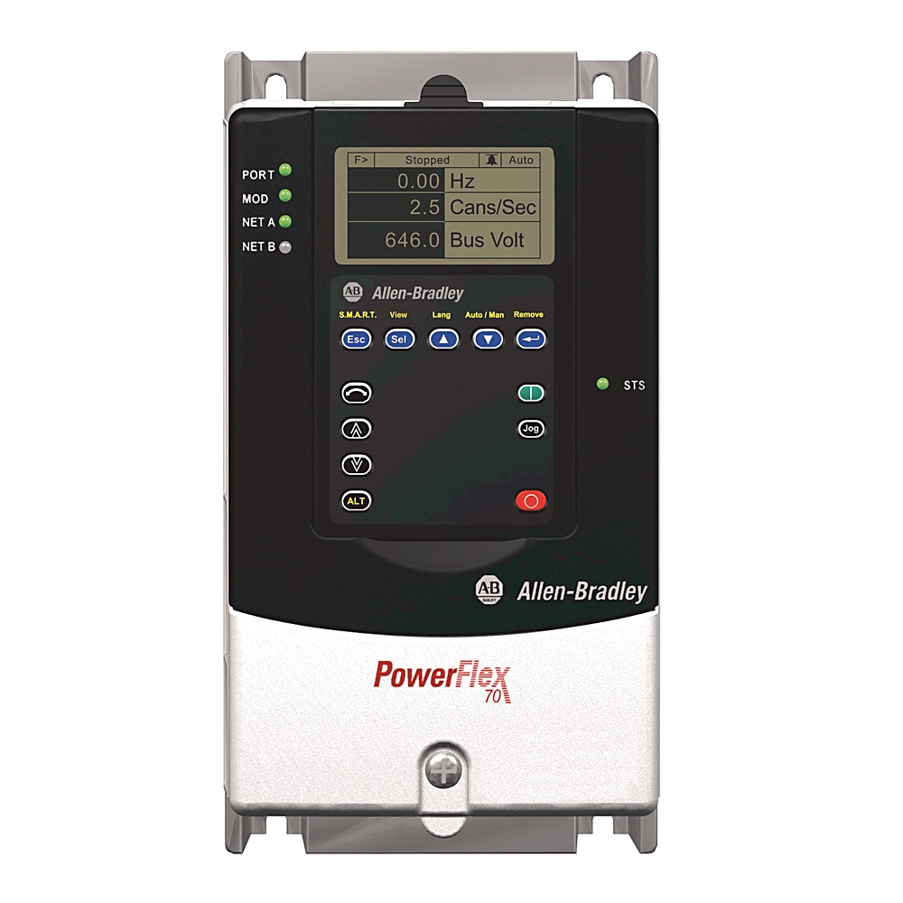
PowerFlex 70 AC 变频器 20A
Serial #:
This product has not been verified. Please register your product to confirm authenticity.
生命周期状态:
产品停产
Rockwell Automation announces that as of May 30, 2027, the PowerFlex 70 AC 变频器 20A will be discontinued and no longer available for sale. Customers are encouraged to remove references to the affected product(s)
停产日期:
May 30, 2027
替代类别:
Engineering Replacement
产品概览
生命周期状态:
产品停产
Rockwell Automation announces that as of May 30, 2027, the PowerFlex 70 AC 变频器 20A will be discontinued and no longer available for sale. Customers are encouraged to remove references to the affected product(s)
停产日期:
May 30, 2027
替代类别:
Engineering Replacement
产品概览
技术规格
基本信息
机械
电气
结构
环境
图纸
文档
认证
配件
替代产品
技术说明
| 制动IGBT |
已安装制动IGBT
|
|---|---|
| 制动电阻 |
无内部
|
| 控制 |
通过24V输入/输出实现增强控制
|
| 反馈选项 |
无反馈
|
| 过滤器选项 |
带EMC滤波器和共模扼流圈
|
| 内部通信模块 |
无通信模块
|
| 子品牌 |
PowerFlex 70 AC 变频器
|
| 防护等级 (IP) |
IP20
|
|---|---|
| 冲击 |
15G峰值,持续时间11ms(11ms(1.0))
|
| 振动 |
0.152mm (0.006″) 位移,1G峰值
|
| 模拟量输出数量 |
1
|
|---|---|
| 主电压 |
400V
|
| 集成制动电阻 |
No
|
| 内部动态制动电阻 |
115欧姆
|
| 制动IGBT |
已安装制动IGBT
|
| 母线欠电压输出关闭 |
305V DC @ 380/400V
|
| 母线欠电压故障等级 |
300V DC @ 380/400V
|
| 内部通信模块 |
无通信模块
|
| AC输入欠电压脱扣 |
233V AC @ 380/400V
|
| 母线电压,标称 |
540V DC @ 380/400V
|
| 母线过电压跳闸 |
810V DC @ 380/400V
|
| 断路器额定电流,最大 |
15A @ 400V AC,三相
|
| 电机电路保护器额定电流,最大 |
3A @ 400V AC,三相
|
| 输出电流额定值(连续) |
1.3A @ 400V AC,三相
|
| 输出电流额定值,1分钟 |
1.4A @ 400V AC,三相
|
| 输出电流额定值,3″ |
1.9A @ 400V AC,三相
|
| 逻辑控制穿越 |
最小0.5 s,典型值2 s
|
| 制动电阻 |
无变频器安装的制动电阻
|
| 输入电流额定值 |
1.6A @ 400V AC,三相
|
| 文档 |
手册
|
| Carrier frequency:载波频率 |
标准控制:2、3、4、5、6、7、8、9和10kHz,矢量控制:2、4、8和12kHz,变频器额定值基于4kHz
|
| 编码器正交 |
90°(27°)
|
| AC输入过电压脱扣 |
475V AC @ 380/400V
|
| 输入功率额定值 |
1.1kVA@400V AC,三相
|
| 双元件延时熔断器额定电流 |
3A @ 400V AC,三相
|
| 非延时熔断器额定电流 |
3~5A @ 400V AC,三相
|
| 散热器热敏电阻 |
由微处理器监控过温跳闸
|
| 变频器与电机功率比,最大 |
建议比例不大于2∶1
|
| 停止模式 |
多种可编程停止模式,包括 - RA、惯性停止、DC制动、快速制动、RA保持和S曲线
|
| 加速/减速 |
两个独立可编程的加速和减速时间。每个时间都可以在0~3600s范围内以0.1s为步进进行编程
|
| 频率精度 |
数字量输入:在设定输出频率的0.01%以内
|
| 数字输入数量 |
6
|
| 数字输出数量 |
2
|
| 内部功率损耗 |
400V @ 0.37Hp 标准负载时为17.9W
|
| 模拟量输入数量 |
2
|
| 电机电压,标称 |
460V @ 380~480V变频器额定值,480V标称线电压
|
| 人机界面模型 |
无 HIM-空白板
|
| 支持的 DeviceNet协议 |
真
|
| 允许在工业区应用 |
真
|
| 外部功率损耗 |
400V @ 0.37Hp 标准负载时为11.5W
|
| 总功率损耗 |
在 400V、0.37Hp 标准负载下为 29.4W
|
| 线电压,标称 |
480V @ 380~480V变频器额定值,460V额定电机电压
|
| 支持 EtherNet/IP协议 |
真
|
| 电源频率 |
50Hz
|
| 输出频率范围 |
标准控制:0~400Hz,增强控制:0~500Hz
|
| 内部EMC滤波 |
符合CE EMC指令(89/336/EEC)的环境滤波器
|
| 反馈选项 |
无反馈
|
| 变频器全功率范围 |
460~528V @ 380~480V 变频器额定值,460V 额定电机电压
|
| 变频器运行范围 |
342~528V @ 380~480V变频器额定值,460V额定电机电压
|
| 扭矩调节 |
无反馈时为 + 10%/−10%,有反馈时为 + 5%/−5%
|
| 机壳类型 |
面板安装 - IP20/NEMA Type 1
|
| 输出电流额定值 |
1.3A,0.37kW标准负载,0.25kW重载,框架A
|
| 冷却风扇运行 |
框架 B、D 和 E:风扇在加电且处于运行状态时运转
|
| 控制选项 |
通过 24V 输入/输出实现增强控制
|
| 变频器过电流跳闸 |
软件电流限制:20~160%额定电流
|
| 效率 |
在额定电流和标称线路电压下为97.5%
|
| 编码器电源 |
5V/12V 可配置 (5) %
|
| 速度控制-速度调节 |
无反馈(矢量控制模式):在120:1速度范围内为基本速度的0.1%,120:1运行范围,30rad/s带宽
|
| 电流限幅能力 |
主动电流限制,可编程范围为额定输出电流的20~160%,比例增益和积分增益可独立编程
|
| 可选电机控制 |
无传感器矢量控制,具备全整定功能。标准V/Hz,具备全定制能力和矢量控制
|
| 频率控制-速度调节 |
滑差补偿(伏特/Hz模式):在40∶1速度范围内为基本速度的0.5%,40∶1运行范围,10rad/s带宽
|
| 输入相 |
三相输入为所有变频器提供满变频器额定值。单相操作提供额定电流的50%。
|
| 控制方法 |
正弦编码PWM,带可编程载波频率。变频器额定值适用于所有变频器
|
| RS-232 硬件接口数量 |
2
|
| RS-485硬件接口数量 |
2
|
| USB 硬件接口数量 |
2
|
| 输出相数 |
3
|
| 输入相数 |
3
|
| 相对对称净电压容差 |
10%
|
| 带控制元件 |
真
|
| 支持TCP/IP协议 |
真
|
| 支持PROFIBUS协议 |
真
|
| 支持的CAN协议 |
真
|
| 支持 Modbus协议 |
真
|
| 允许在家庭和商业领域应用 |
真
|
| 电机过载保护 |
符合NEC第430条规定的10级电机过载保护和NEC第430.126(A)(2)条规定的电机过热保护。UL 508C文件E59272
|
| 输入频率范围 |
47 Hz
|
| 编码器占空比 |
50%(10%)
|
| 电压容差 |
−10%
|
| 位移功率因数(所有变频器) |
在整个速度范围内为0.98
|
| 最大短路额定值 |
200000A 对称
|
| 输出电压范围 |
0至电机额定电压
|
| 编码器类型 |
增量式,双通道
|
| 电源穿越 |
满载时为15ms
|
| 短路脱扣 |
变频器输出相间
|
| 接地故障脱扣 |
驱动器输出相对地
|
| 变频器与电机功率比,最小值 |
建议比例不小于1∶2
|
| 控制逻辑抗扰度 |
喷射式弧瞬态高达1500V峰值
|
| 线路瞬变 |
高达6000V峰值,符合IEEE C62.41-1991标准
|
| 短路电流额定值,最大 |
最大短路电流额定值,以匹配指定的熔断器/断路器能力
|
| 间歇过载 |
110%过载能力,持续时间最长1min;150%过载能力,持续时间最长3s
|
| 高度,约 |
IP20,NEMA/UL Type 1:225.7mm
|
|---|---|
| 深度,约 |
IP20,NEMA/UL Type 1:179.8mm
|
| 宽度,约 |
IP20,NEMA/UL Type 1:122.4mm
|
| 重量,约 |
IP20,NEMA/UL 类型 1:2.71kg
|
| 海拔高度 |
最大1000m (3300′),无降额
|
|---|---|
| 防护等级(NEMA) |
1
|
| 周围空气温度,最大 |
IP20,NEMA/UL 类型 1:0~50°C (32~122°F),无降额
|
| 大气 |
变频器不得安装在环境大气中含有挥发性或腐蚀性气体、蒸汽或灰尘的区域。如果变频器不会立即安装,应将其存放在不暴露于腐蚀性环境的地方。
|
| 储存温度 |
−40°C
|
| 相对湿度 |
5~95% 无凝露
|
| 根据 EN 61800-5-1,污染等级为1 |
无污染,仅发生干燥非传导污染,无影响
|
| 根据 EN 61800-5-1,污染等级为4 |
污染会产生持续的导电性,例如由导电性粉尘、雨或雪引起的
|
| 根据 EN 61800-5-1,污染等级为3 |
发生导电污染、干燥非传导污染以及因冷凝而变成导电污染
|
| 根据 EN 61800-5-1,污染等级为2 |
通常只会发生非传导污染,当变频器停止工作时,偶尔会因冷凝而出现临时导电性污染
|
| 周围环境污染等级 |
所有机壳均适用于污染等级1和2,污染等级3和4需要满足或超过IP54、NEMA/UL类型12的机壳
|
| 图纸 | |
|---|---|
| PowerTerminal Block Drawing 电源端子块图 | 下载 (PDF) |
| 尺寸图(目录页面) | 下载 (PDF) |
| 控制端子块图 | 下载 (PDF) |
| 2D尺寸图(DWG/DXF) | 下载 (ZIP) |
| 2D尺寸图(PDF) | 下载 (PDF) |
| 3D STEP (STP)模型 | 下载 (ZIP) |
| 图纸 |
|---|
| PowerTerminal Block Drawing 电源端子块图 下载 (PDF) |
| 尺寸图(目录页面) 下载 (PDF) |
| 控制端子块图 下载 (PDF) |
| 2D尺寸图(DWG/DXF) 下载 (ZIP) |
| 2D尺寸图(PDF) 下载 (PDF) |
| 3D STEP (STP)模型 下载 (ZIP) |
登录您的罗克韦尔自动化帐户以查看和下载技术图纸.
登录
| 参考手册 | 出版 |
|---|---|
| REFERENCE_MANUAL_pflex-rm004_-en-e | PFLEX-RM004 |
| 基本信息 | 出版 |
|---|---|
| 导线规格表 | -- |
| PowerFlex 70 700 参考手册-第1卷 | PFLEX-RM001 |
| 技术规格表 | -- |
| 产品宣传册 | -- |
| 用户手册文档更新 | -- |
| 熔断器尺寸表 | -- |
| 产品简介 | -- |
| 产品简介 | -- |
| 参数列表 | -- |
| 例行维护指南 | -- |
| 用户手册 | -- |
| 驱动器规格 | -- |
| 安装说明 | 出版 |
|---|---|
| INSTALLATION_INSTRUCTIONS_20a-in002_-mu-p | 20A-IN002 |
| 应用技巧 | 出版 |
|---|---|
| APPLICATION_TECHNIQUES_pflex-at001_-en-p | PFLEX-AT001 |
| 快速参考 | 出版 |
|---|---|
| QUICK_REFERENCE_20him-qr001_-mu-p | 20HIM-QR001 |
| 技术数据 | 出版 |
|---|---|
| 20a-td001_-en-p | 20A-TD001 |
| 接线图 | 出版 |
|---|---|
| WIRING_DIAGRAM_21vw-wd002_-en-p | 21VW-WD002 |
| 用户手册 | 出版 |
|---|---|
| USER_MANUAL_20a-um001_-en-p | 20A-UM001 |
- 欧亚经济共同体
- CE
- 韩国KC
- 劳氏船级社
- 澳大利亚RCM
- 安全
- 地震
- 半导体行业抗扰度
- UL认证
- 英国安全证书
截至 2026-03-24,此产品已获得上述多项认证。此日期前后销售的产品,所获认证可能有所不同。请查阅产品标签,确认具体产品所持有的相关认证。
每页项目:
每页项目:
| 技术说明 |
|---|
技术规格
| 制动IGBT |
已安装制动IGBT
|
|---|---|
| 制动电阻 |
无内部
|
| 控制 |
通过24V输入/输出实现增强控制
|
| 反馈选项 |
无反馈
|
| 过滤器选项 |
带EMC滤波器和共模扼流圈
|
| 内部通信模块 |
无通信模块
|
| 子品牌 |
PowerFlex 70 AC 变频器
|
| 防护等级 (IP) |
IP20
|
|---|---|
| 冲击 |
15G峰值,持续时间11ms(11ms(1.0))
|
| 振动 |
0.152mm (0.006″) 位移,1G峰值
|
| 模拟量输出数量 |
1
|
|---|---|
| 主电压 |
400V
|
| 集成制动电阻 |
No
|
| 内部动态制动电阻 |
115欧姆
|
| 制动IGBT |
已安装制动IGBT
|
| 母线欠电压输出关闭 |
305V DC @ 380/400V
|
| 母线欠电压故障等级 |
300V DC @ 380/400V
|
| 内部通信模块 |
无通信模块
|
| AC输入欠电压脱扣 |
233V AC @ 380/400V
|
| 母线电压,标称 |
540V DC @ 380/400V
|
| 母线过电压跳闸 |
810V DC @ 380/400V
|
| 断路器额定电流,最大 |
15A @ 400V AC,三相
|
| 电机电路保护器额定电流,最大 |
3A @ 400V AC,三相
|
| 输出电流额定值(连续) |
1.3A @ 400V AC,三相
|
| 输出电流额定值,1分钟 |
1.4A @ 400V AC,三相
|
| 输出电流额定值,3″ |
1.9A @ 400V AC,三相
|
| 逻辑控制穿越 |
最小0.5 s,典型值2 s
|
| 制动电阻 |
无变频器安装的制动电阻
|
| 输入电流额定值 |
1.6A @ 400V AC,三相
|
| 文档 |
手册
|
| Carrier frequency:载波频率 |
标准控制:2、3、4、5、6、7、8、9和10kHz,矢量控制:2、4、8和12kHz,变频器额定值基于4kHz
|
| 编码器正交 |
90°(27°)
|
| AC输入过电压脱扣 |
475V AC @ 380/400V
|
| 输入功率额定值 |
1.1kVA@400V AC,三相
|
| 双元件延时熔断器额定电流 |
3A @ 400V AC,三相
|
| 非延时熔断器额定电流 |
3~5A @ 400V AC,三相
|
| 散热器热敏电阻 |
由微处理器监控过温跳闸
|
| 变频器与电机功率比,最大 |
建议比例不大于2∶1
|
| 停止模式 |
多种可编程停止模式,包括 - RA、惯性停止、DC制动、快速制动、RA保持和S曲线
|
| 加速/减速 |
两个独立可编程的加速和减速时间。每个时间都可以在0~3600s范围内以0.1s为步进进行编程
|
| 频率精度 |
数字量输入:在设定输出频率的0.01%以内
|
| 数字输入数量 |
6
|
| 数字输出数量 |
2
|
| 内部功率损耗 |
400V @ 0.37Hp 标准负载时为17.9W
|
| 模拟量输入数量 |
2
|
| 电机电压,标称 |
460V @ 380~480V变频器额定值,480V标称线电压
|
| 人机界面模型 |
无 HIM-空白板
|
| 支持的 DeviceNet协议 |
真
|
| 允许在工业区应用 |
真
|
| 外部功率损耗 |
400V @ 0.37Hp 标准负载时为11.5W
|
| 总功率损耗 |
在 400V、0.37Hp 标准负载下为 29.4W
|
| 线电压,标称 |
480V @ 380~480V变频器额定值,460V额定电机电压
|
| 支持 EtherNet/IP协议 |
真
|
| 电源频率 |
50Hz
|
| 输出频率范围 |
标准控制:0~400Hz,增强控制:0~500Hz
|
| 内部EMC滤波 |
符合CE EMC指令(89/336/EEC)的环境滤波器
|
| 反馈选项 |
无反馈
|
| 变频器全功率范围 |
460~528V @ 380~480V 变频器额定值,460V 额定电机电压
|
| 变频器运行范围 |
342~528V @ 380~480V变频器额定值,460V额定电机电压
|
| 扭矩调节 |
无反馈时为 + 10%/−10%,有反馈时为 + 5%/−5%
|
| 机壳类型 |
面板安装 - IP20/NEMA Type 1
|
| 输出电流额定值 |
1.3A,0.37kW标准负载,0.25kW重载,框架A
|
| 冷却风扇运行 |
框架 B、D 和 E:风扇在加电且处于运行状态时运转
|
| 控制选项 |
通过 24V 输入/输出实现增强控制
|
| 变频器过电流跳闸 |
软件电流限制:20~160%额定电流
|
| 效率 |
在额定电流和标称线路电压下为97.5%
|
| 编码器电源 |
5V/12V 可配置 (5) %
|
| 速度控制-速度调节 |
无反馈(矢量控制模式):在120:1速度范围内为基本速度的0.1%,120:1运行范围,30rad/s带宽
|
| 电流限幅能力 |
主动电流限制,可编程范围为额定输出电流的20~160%,比例增益和积分增益可独立编程
|
| 可选电机控制 |
无传感器矢量控制,具备全整定功能。标准V/Hz,具备全定制能力和矢量控制
|
| 频率控制-速度调节 |
滑差补偿(伏特/Hz模式):在40∶1速度范围内为基本速度的0.5%,40∶1运行范围,10rad/s带宽
|
| 输入相 |
三相输入为所有变频器提供满变频器额定值。单相操作提供额定电流的50%。
|
| 控制方法 |
正弦编码PWM,带可编程载波频率。变频器额定值适用于所有变频器
|
| RS-232 硬件接口数量 |
2
|
| RS-485硬件接口数量 |
2
|
| USB 硬件接口数量 |
2
|
| 输出相数 |
3
|
| 输入相数 |
3
|
| 相对对称净电压容差 |
10%
|
| 带控制元件 |
真
|
| 支持TCP/IP协议 |
真
|
| 支持PROFIBUS协议 |
真
|
| 支持的CAN协议 |
真
|
| 支持 Modbus协议 |
真
|
| 允许在家庭和商业领域应用 |
真
|
| 电机过载保护 |
符合NEC第430条规定的10级电机过载保护和NEC第430.126(A)(2)条规定的电机过热保护。UL 508C文件E59272
|
| 输入频率范围 |
47 Hz
|
| 编码器占空比 |
50%(10%)
|
| 电压容差 |
−10%
|
| 位移功率因数(所有变频器) |
在整个速度范围内为0.98
|
| 最大短路额定值 |
200000A 对称
|
| 输出电压范围 |
0至电机额定电压
|
| 编码器类型 |
增量式,双通道
|
| 电源穿越 |
满载时为15ms
|
| 短路脱扣 |
变频器输出相间
|
| 接地故障脱扣 |
驱动器输出相对地
|
| 变频器与电机功率比,最小值 |
建议比例不小于1∶2
|
| 控制逻辑抗扰度 |
喷射式弧瞬态高达1500V峰值
|
| 线路瞬变 |
高达6000V峰值,符合IEEE C62.41-1991标准
|
| 短路电流额定值,最大 |
最大短路电流额定值,以匹配指定的熔断器/断路器能力
|
| 间歇过载 |
110%过载能力,持续时间最长1min;150%过载能力,持续时间最长3s
|
| 高度,约 |
IP20,NEMA/UL Type 1:225.7mm
|
|---|---|
| 深度,约 |
IP20,NEMA/UL Type 1:179.8mm
|
| 宽度,约 |
IP20,NEMA/UL Type 1:122.4mm
|
| 重量,约 |
IP20,NEMA/UL 类型 1:2.71kg
|
| 海拔高度 |
最大1000m (3300′),无降额
|
|---|---|
| 防护等级(NEMA) |
1
|
| 周围空气温度,最大 |
IP20,NEMA/UL 类型 1:0~50°C (32~122°F),无降额
|
| 大气 |
变频器不得安装在环境大气中含有挥发性或腐蚀性气体、蒸汽或灰尘的区域。如果变频器不会立即安装,应将其存放在不暴露于腐蚀性环境的地方。
|
| 储存温度 |
−40°C
|
| 相对湿度 |
5~95% 无凝露
|
| 根据 EN 61800-5-1,污染等级为1 |
无污染,仅发生干燥非传导污染,无影响
|
| 根据 EN 61800-5-1,污染等级为4 |
污染会产生持续的导电性,例如由导电性粉尘、雨或雪引起的
|
| 根据 EN 61800-5-1,污染等级为3 |
发生导电污染、干燥非传导污染以及因冷凝而变成导电污染
|
| 根据 EN 61800-5-1,污染等级为2 |
通常只会发生非传导污染,当变频器停止工作时,偶尔会因冷凝而出现临时导电性污染
|
| 周围环境污染等级 |
所有机壳均适用于污染等级1和2,污染等级3和4需要满足或超过IP54、NEMA/UL类型12的机壳
|
图纸
| 图纸 | |
|---|---|
| PowerTerminal Block Drawing 电源端子块图 | 下载 (PDF) |
| 尺寸图(目录页面) | 下载 (PDF) |
| 控制端子块图 | 下载 (PDF) |
| 2D尺寸图(DWG/DXF) | 下载 (ZIP) |
| 2D尺寸图(PDF) | 下载 (PDF) |
| 3D STEP (STP)模型 | 下载 (ZIP) |
| 图纸 |
|---|
| PowerTerminal Block Drawing 电源端子块图 下载 (PDF) |
| 尺寸图(目录页面) 下载 (PDF) |
| 控制端子块图 下载 (PDF) |
| 2D尺寸图(DWG/DXF) 下载 (ZIP) |
| 2D尺寸图(PDF) 下载 (PDF) |
| 3D STEP (STP)模型 下载 (ZIP) |
登录您的罗克韦尔自动化帐户以查看和下载技术图纸.
登录
文档
|
REFERENCE_MANUAL_pflex-rm004_-en-e
参考手册
PFLEX-RM004 |
|
导线规格表
基本信息
-- |
|
PowerFlex 70 700 参考手册-第1卷
基本信息
PFLEX-RM001 |
|
技术规格表
基本信息
-- |
|
产品宣传册
基本信息
-- |
|
用户手册文档更新
基本信息
-- |
|
熔断器尺寸表
基本信息
-- |
|
产品简介
基本信息
-- |
|
产品简介
基本信息
-- |
|
参数列表
基本信息
-- |
|
例行维护指南
基本信息
-- |
|
用户手册
基本信息
-- |
|
驱动器规格
基本信息
-- |
|
INSTALLATION_INSTRUCTIONS_20a-in002_-mu-p
安装说明
20A-IN002 |
|
APPLICATION_TECHNIQUES_pflex-at001_-en-p
应用技巧
PFLEX-AT001 |
|
QUICK_REFERENCE_20him-qr001_-mu-p
快速参考
20HIM-QR001 |
|
20a-td001_-en-p
技术数据
20A-TD001 |
|
WIRING_DIAGRAM_21vw-wd002_-en-p
接线图
21VW-WD002 |
|
USER_MANUAL_20a-um001_-en-p
用户手册
20A-UM001 |
| 参考手册 | 出版 |
|---|---|
| REFERENCE_MANUAL_pflex-rm004_-en-e | PFLEX-RM004 |
| 基本信息 | 出版 |
| 导线规格表 | -- |
| PowerFlex 70 700 参考手册-第1卷 | PFLEX-RM001 |
| 技术规格表 | -- |
| 产品宣传册 | -- |
| 用户手册文档更新 | -- |
| 熔断器尺寸表 | -- |
| 产品简介 | -- |
| 产品简介 | -- |
| 参数列表 | -- |
| 例行维护指南 | -- |
| 用户手册 | -- |
| 驱动器规格 | -- |
| 安装说明 | 出版 |
| INSTALLATION_INSTRUCTIONS_20a-in002_-mu-p | 20A-IN002 |
| 应用技巧 | 出版 |
| APPLICATION_TECHNIQUES_pflex-at001_-en-p | PFLEX-AT001 |
| 快速参考 | 出版 |
| QUICK_REFERENCE_20him-qr001_-mu-p | 20HIM-QR001 |
| 技术数据 | 出版 |
| 20a-td001_-en-p | 20A-TD001 |
| 接线图 | 出版 |
| WIRING_DIAGRAM_21vw-wd002_-en-p | 21VW-WD002 |
| 用户手册 | 出版 |
| USER_MANUAL_20a-um001_-en-p | 20A-UM001 |
认证
- 欧亚经济共同体
- CE
- 韩国KC
- 劳氏船级社
- 澳大利亚RCM
- 安全
- 地震
- 半导体行业抗扰度
- UL认证
- 英国安全证书
截至 2026-03-24,此产品已获得上述多项认证。此日期前后销售的产品,所获认证可能有所不同。请查阅产品标签,确认具体产品所持有的相关认证。
配件
每页项目:
替代产品
每页项目:
技术说明
| 技术说明 |
|---|
PowerFlex 70 AC 变频器 20A
20AC1P3A0AYNANC0
关闭
打印
Copyright ©2026 Rockwell Automation, Inc.
本网站上的内容已使用为人工智能 (AI) 翻译,未经人工审核或编辑。内容可能包含错误或不准确之处,并按“原样”提供,不提供任何形式的担保。英文版本内容为正式文本是内容的英文版本。