生命周期状态:
活跃
Description
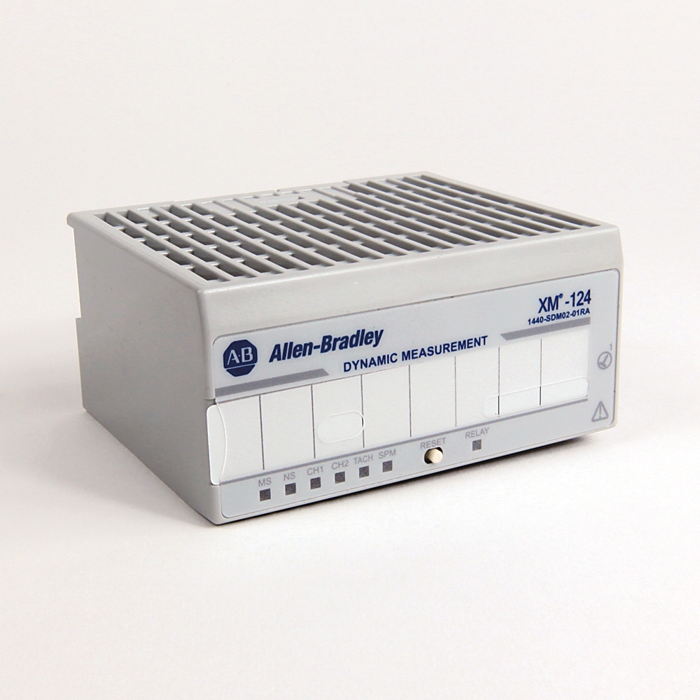
1440-SDM02-01RA:XM-124标准动态测量模块
首选
1440-SDM02-01RA
XM-124 Standard Dynamic Measurement Mdl
Serial #:
此产品尚未验证,请{}确认真实性
注册您的产品
生命周期状态:
活跃
Description
1440-SDM02-01RA:XM-124标准动态测量模块
概述
Electrical & Connectivity
General Features
Power & Electrical Characteristics
Inputs & Outputs (I/O)
Relays & Control Outputs
Communication & Interfaces
Technical Specifications
Measurement & Parameters
Alarms & Fault Management
Signal Processing & Conditioning
Data Handling
Compliance & Environment
Standards & Protection
Physical Characteristics
Construction
Mechanical
Module
技术规格
Tachometer input
文档
下载
认证
替代产品
技术说明
| 唯一产品序列号 |
1440-SDM02-01RA
|
|---|---|
| 通用产品代码(UPC) |
884951743045
|
| 预计交期 |
5 天
|
| 标准保修期 |
1年 查看详情 |
| 原产国 |
美利坚合众国
|
| Nonvolatile configuration |
A copy of the module configuration is retained in nonvolatile memory from which the configuration is loaded upon powerup, The configuration that is stored in nonvolatile memory can be deleted only by a module-reset,command that is sent via a serial interf
|
|---|---|
| Output |
2
|
| Status indicator |
Module, Network, Channel 1, Channel 2, Tachom, Setpoint multiplier, Virtual relay
|
| Transducer Power |
IEPE Accel, ECP's, Volts
|
| Ethernet |
False
|
|---|---|
| Isolation voltage |
50V (continuous), basic insulation type between uninsulated live parts and the enclosure with the relay contacts open and closed, Type tested at 707V DC @ 60s between uninsulated live parts and the enclosure with the relay contacts open and closed, Typ
|
| Model |
Basic device
|
| Number of indicator outputs |
7
|
| Number of sensor inputs for IEPE sensors |
2
|
| Suitable for bus connection |
True
|
| Type of electric connection |
Screw connection
|
| Voltage type of supply voltage |
DC
|
Input Signals
| Sensitivity |
Up to 15% from nom
|
|---|---|
| Transducer power |
Constant voltage: 24V DC, -24V DC @ 40mA, Constant current 4.5 mA ± 30% / -20% from 24V DC (IEPE), None (voltage input), Tachom can be powered, constant voltage, or configured as voltage input
|
| Two dynamic channel inputs |
Eddy current transducer signals, Accelerom signals, Voltage signals from any dynamic measurement sensor, such as velocity or pressure transducer
|
| Voltage ranges |
-20…0V DC, -10...10V DC, 0…20V DC
|
Output Signals
| 4...20 mA outputs |
Each output is independently progmed to represent any measured param, from either channel, Two isolated outputs, 300 Ω max load
|
|---|---|
| Buffered outputs |
One active buffer per dynamic channel, One resistive buffer for tachom
|
| Activation on |
Alarm Status: Normal, Alert, Danger, Disarm, Transducer fault, Module fault, Tacho fault
|
|---|---|
| Expected life (min operations) |
Mechanical: 2x10^7, Electrical @ 20 cpm, 1.5A @ 24V DC: 10^5
|
| Logic |
Single or paired AND or OR logic that is applied to any alarm
|
| Peak speed capture |
The XM-124 retains the value of the highest speed that is observed since module power was cycled or the peak speed value was manually reset
|
| Rating (resistive) |
Capacity, nominal: 1.5A @ 24V DC, Capacity, min 100 µA @ 100 mV DC, Power, max 41.4 W, Voltage, max 27.6V DC, Current, max 1.5 A
|
| Reset |
Local reset switch on top of module, Remote reset switch that is wired to terminal base, Digital reset command via serial or DeviceNet interface
|
| Time delay |
0…25.5 s, adjustable in 100 ms increments
|
| DeviceNet network |
Standard DeviceNet protocol for all functions (not power-module power is provided independently), Available EDS file supports most DeviceNet compliant systems, Communication rate that is set automatically by bus master to 125 Kbps, 250 Kbps, or 500 Kbps,
|
|---|---|
| Serial |
RS-232 via mini-connector or terminal base unit, Communication rate that is fixed at 19.2 Kbps, Local configuration via the Serial Configuration Utility
|
Measurement Types & Capabilities
| FFT derived |
FFT bands, Four bands per channel, Defined in frequency or order domain, Overall or max peak in band, Orders, Magnitude: 1x, 2x, 3x, Phase: 1x, 2x, Not 1x, Sum harmonics
|
|---|---|
| Real time |
Overall, RMS, Peak (true or calculated), Peak-to-peak (true or calculated), gSE, Optional low pass filter, -3 dB corner: 200 Hz...20 kHz, Roll off: -24 dB/octave, Gap (or transducer bias voltage), Speed, SMAX magnitude, SMAX phase, Band pass filter value,
|
| Type |
FFT and time waveform, Asynchronous or synchronous
|
Alarms
| Alarm parameters |
Any measured param
|
|---|---|
| Failsafe |
Normally energized (fail-safe), Normally de-energized (non-failsafe)
|
| Hysteresis |
User configurable in software
|
| Latching |
Latching, non-latching
|
| Number |
Sixteen alarm and danger pairs
|
| Operators |
Greater than, Less than, Inside range, Outside range
|
| Speed inhibit |
A speed range can be specified for each alarm. When applied, the alarm is disabled when speed is outside of the defined range.
|
| Startup inhibit/setpoint multiplication |
Period: 0...1092 min, adjustable in 0.1 min increments, Inhibit/multiplication function, Multiply by N (0...10, 0 = Disarm)
|
| Band pass digital filter |
Independently configured per channel, Frequency, min 25...1000 Hz, Frequency, max 100…5500 Hz, Roll off: -60 dB/octave
|
|---|---|
| FFT lines |
100, 200, 400, 800, 1600
|
| High pass analog filters |
-3 dB corners: 0.2, 1, 5, 10, 40 Hz, Roll off: -30 dB/octave for the 0.2 Hz filter, otherwise 24 dB/octave
|
| Integration |
None, single or double
|
| Low pass analog filter |
Applied to integrated acceleration measurements, -3 dB corner: 5 kHz, roll off: -18 dB/octave
|
| Low pass digital filter |
Independently configured per channel, Optional Overall LP Filter, 100...20000 Hz, Spike Energy, Spectra FMAX: 10...5000 Hz, Roll Off: -24 dB/octave
|
| Resolution |
A/D conversion: 24 bit, Dynamic range: 80 dbfs (0.01% fs), 90 dbfs, typical
|
| Sampling mode |
Selectable per channel, Dynamic Measurements, Asynchronous, FMAX: 1 Hz…20 kHz, Synchronous, Order range: 4…200, FMAX: 10 Hz…5000 Hz, Measured: orders x speed (Hz), Spike Energy, Static Measurements, Eccentricity, Peak-to-Peak Eccentricity, Thrust, Normal
|
| Tracking digital filter |
Independently configured per channel, Tracked speed multiple: 0.1...20.0 times the measured (tachom) rpm, Constant Q: 1...200, Constant bandwidth: 0.1...25 Hz, Roll off: -36 dB/octave, Typical
|
| Units |
G, ips, mm/s, mils, µm, PSI, mbar, volt
|
Data
| Accuracy, min |
±1% of full scale range for the channel, ±1% of alarm setpoint for speed
|
|---|---|
| Complex data |
Spectra (synchronous or asynchronous), Waveform (synchronous or asynchronous), Simultaneous waveforms (synchronous), gSE Spectra
|
| Delta rpm buffer |
Number of records: 512, Delta speed interval: 1…3600 rpm, Trigger mode: Startup collects data in increasing rpm direction only, coast-down collects data in both increasing and decreasing directions, The data that is collected in the buffer is user configu
|
| Delta time buffer |
Number of records: 2048, Delta time interval: 1…3600 s, Trigger mode: Relay is activated or trigger event (such as DeviceNet command from a controller or host)
|
| Spectra or waveform |
Saved upon same trigger as delta time buffer
|
| Conducted RF immunity |
10V rms with 1 kHz sine-wave 80% AM from 150 kHz...80 MHz
|
|---|---|
| EFT/B immunity |
±3kV @ 5kHz on power ports, ±3kV @ 5kH on signal ports, ±3kV @ 5kHz on DeviceNet ports
|
| ESD immunity |
6 kV contact discharges, 8 kV air discharges
|
| Emissions |
Class A
|
| Operating temperature |
-20 °C
|
| Radiated RF immunity |
10 V/m with 1 kHz sine-wave 80% AM from 80...2000 MHz, 10 V/m with 200 Hz 50% Pulse 100% AM @ 900 MHz, 10 V/m with 200 Hz 50% Pulse 100% AM @ 1890 MHz, 3 V/m with 1 kHz sine-wave 80% AM from 2000...2700 MHz
|
| Relative humidity |
5...95% noncondensing
|
| Shock |
Opsal: 15 G
|
| Storage temperature |
-40 °C
|
| Surge transient immunity |
±1 kV line-line (DM) and ±2 kV line-earth (CM) on power and relay ports, ±2 kV line-earth (CM) on shielded signal ports, ±2 kV line-earth (CM) on DeviceNet ports
|
| Surrounding air temperature, max |
65 °C
|
| Vibration |
5 G @ 10...500 Hz
|
Construction
| Enclosure type rating |
None (open-style)
|
|---|---|
| Modular expandable |
True
|
| Number of rotational speed inputs |
1
|
| Type of fastening |
Direct mounting
|
Mechanical
| Depth |
94 mm
|
|---|---|
| Height |
97 mm
|
| Weight |
Module: 0.172 kg (0.38 lb), Terminal base: 0.172 kg (0.38 lb)
|
| Width |
94 mm
|
Construction
| Power dissipation, max |
8.7 W
|
|---|---|
| Power supply |
24V DC @ 350mA, Requires Class 2/SELV/PELV power supply
|
| Wiring category |
2 - on signal ports, 1 - on power and relay ports, 2 - on DeviceNet ports, 3 - on serial ports
|
| Input impedance |
>120 kΩ
|
|---|---|
| One tachometer input |
±25V (50V max peak-to-peak), 1...50,000 events/revolution
|
| Pulses per revolution |
0 (tach off)…50,000
|
| Range |
1...1,200,000 rpm, 0.0167…20,000 Hz
|
| Rate of change of speed, max |
500 Hz/s
|
版本:
发布说明
| Firmware | 大小 | 备注 | |
|---|---|---|---|
|
|
Firmware for 1440-SDM02-01RA v8.000 | 266 KB | |
| Accessory Files | 大小 | 备注 | |
|
|
EDS for 1440-SDM02-01RA/XM-124 EDS V7.00x | 527 KB | |
| EDS - Electronic Data Sheet Files | 大小 | 备注 | |
|
|
EDS files for 1440-SDM02-01RA (multi) | 22.51 KB | |
|
|
EDS files for XM Family (multi) | 583 KB | |


截至 2026-08-11,此产品已获得上述多项认证。此日期前后销售的产品,所获认证可能有所不同。请查阅产品标签,确认具体产品所持有的相关认证。
正在查找认证文件?
请浏览我们内容详尽的资料库,查看该产品及其他产品的认证信息。
法规信息
| 欧盟进口商地址 |
Rockwell Automation N.V |
|---|---|
| 欧盟授权代表地址 |
Rockwell Automation N.V |
每页项目:
| 技术说明 |
|---|
概述
| 唯一产品序列号 |
1440-SDM02-01RA
|
|---|---|
| 通用产品代码(UPC) |
884951743045
|
| 预计交期 |
5 天
|
| 标准保修期 |
1年 查看详情 |
| 原产国 |
美利坚合众国
|
Electrical & Connectivity
| Nonvolatile configuration |
A copy of the module configuration is retained in nonvolatile memory from which the configuration is loaded upon powerup, The configuration that is stored in nonvolatile memory can be deleted only by a module-reset,command that is sent via a serial interf
|
|---|---|
| Output |
2
|
| Status indicator |
Module, Network, Channel 1, Channel 2, Tachom, Setpoint multiplier, Virtual relay
|
| Transducer Power |
IEPE Accel, ECP's, Volts
|
| Ethernet |
False
|
|---|---|
| Isolation voltage |
50V (continuous), basic insulation type between uninsulated live parts and the enclosure with the relay contacts open and closed, Type tested at 707V DC @ 60s between uninsulated live parts and the enclosure with the relay contacts open and closed, Typ
|
| Model |
Basic device
|
| Number of indicator outputs |
7
|
| Number of sensor inputs for IEPE sensors |
2
|
| Suitable for bus connection |
True
|
| Type of electric connection |
Screw connection
|
| Voltage type of supply voltage |
DC
|
Input Signals
| Sensitivity |
Up to 15% from nom
|
|---|---|
| Transducer power |
Constant voltage: 24V DC, -24V DC @ 40mA, Constant current 4.5 mA ± 30% / -20% from 24V DC (IEPE), None (voltage input), Tachom can be powered, constant voltage, or configured as voltage input
|
| Two dynamic channel inputs |
Eddy current transducer signals, Accelerom signals, Voltage signals from any dynamic measurement sensor, such as velocity or pressure transducer
|
| Voltage ranges |
-20…0V DC, -10...10V DC, 0…20V DC
|
Output Signals
| 4...20 mA outputs |
Each output is independently progmed to represent any measured param, from either channel, Two isolated outputs, 300 Ω max load
|
|---|---|
| Buffered outputs |
One active buffer per dynamic channel, One resistive buffer for tachom
|
| Activation on |
Alarm Status: Normal, Alert, Danger, Disarm, Transducer fault, Module fault, Tacho fault
|
|---|---|
| Expected life (min operations) |
Mechanical: 2x10^7, Electrical @ 20 cpm, 1.5A @ 24V DC: 10^5
|
| Logic |
Single or paired AND or OR logic that is applied to any alarm
|
| Peak speed capture |
The XM-124 retains the value of the highest speed that is observed since module power was cycled or the peak speed value was manually reset
|
| Rating (resistive) |
Capacity, nominal: 1.5A @ 24V DC, Capacity, min 100 µA @ 100 mV DC, Power, max 41.4 W, Voltage, max 27.6V DC, Current, max 1.5 A
|
| Reset |
Local reset switch on top of module, Remote reset switch that is wired to terminal base, Digital reset command via serial or DeviceNet interface
|
| Time delay |
0…25.5 s, adjustable in 100 ms increments
|
| DeviceNet network |
Standard DeviceNet protocol for all functions (not power-module power is provided independently), Available EDS file supports most DeviceNet compliant systems, Communication rate that is set automatically by bus master to 125 Kbps, 250 Kbps, or 500 Kbps,
|
|---|---|
| Serial |
RS-232 via mini-connector or terminal base unit, Communication rate that is fixed at 19.2 Kbps, Local configuration via the Serial Configuration Utility
|
技术规格
Measurement Types & Capabilities
| FFT derived |
FFT bands, Four bands per channel, Defined in frequency or order domain, Overall or max peak in band, Orders, Magnitude: 1x, 2x, 3x, Phase: 1x, 2x, Not 1x, Sum harmonics
|
|---|---|
| Real time |
Overall, RMS, Peak (true or calculated), Peak-to-peak (true or calculated), gSE, Optional low pass filter, -3 dB corner: 200 Hz...20 kHz, Roll off: -24 dB/octave, Gap (or transducer bias voltage), Speed, SMAX magnitude, SMAX phase, Band pass filter value,
|
| Type |
FFT and time waveform, Asynchronous or synchronous
|
Alarms
| Alarm parameters |
Any measured param
|
|---|---|
| Failsafe |
Normally energized (fail-safe), Normally de-energized (non-failsafe)
|
| Hysteresis |
User configurable in software
|
| Latching |
Latching, non-latching
|
| Number |
Sixteen alarm and danger pairs
|
| Operators |
Greater than, Less than, Inside range, Outside range
|
| Speed inhibit |
A speed range can be specified for each alarm. When applied, the alarm is disabled when speed is outside of the defined range.
|
| Startup inhibit/setpoint multiplication |
Period: 0...1092 min, adjustable in 0.1 min increments, Inhibit/multiplication function, Multiply by N (0...10, 0 = Disarm)
|
| Band pass digital filter |
Independently configured per channel, Frequency, min 25...1000 Hz, Frequency, max 100…5500 Hz, Roll off: -60 dB/octave
|
|---|---|
| FFT lines |
100, 200, 400, 800, 1600
|
| High pass analog filters |
-3 dB corners: 0.2, 1, 5, 10, 40 Hz, Roll off: -30 dB/octave for the 0.2 Hz filter, otherwise 24 dB/octave
|
| Integration |
None, single or double
|
| Low pass analog filter |
Applied to integrated acceleration measurements, -3 dB corner: 5 kHz, roll off: -18 dB/octave
|
| Low pass digital filter |
Independently configured per channel, Optional Overall LP Filter, 100...20000 Hz, Spike Energy, Spectra FMAX: 10...5000 Hz, Roll Off: -24 dB/octave
|
| Resolution |
A/D conversion: 24 bit, Dynamic range: 80 dbfs (0.01% fs), 90 dbfs, typical
|
| Sampling mode |
Selectable per channel, Dynamic Measurements, Asynchronous, FMAX: 1 Hz…20 kHz, Synchronous, Order range: 4…200, FMAX: 10 Hz…5000 Hz, Measured: orders x speed (Hz), Spike Energy, Static Measurements, Eccentricity, Peak-to-Peak Eccentricity, Thrust, Normal
|
| Tracking digital filter |
Independently configured per channel, Tracked speed multiple: 0.1...20.0 times the measured (tachom) rpm, Constant Q: 1...200, Constant bandwidth: 0.1...25 Hz, Roll off: -36 dB/octave, Typical
|
| Units |
G, ips, mm/s, mils, µm, PSI, mbar, volt
|
Data
| Accuracy, min |
±1% of full scale range for the channel, ±1% of alarm setpoint for speed
|
|---|---|
| Complex data |
Spectra (synchronous or asynchronous), Waveform (synchronous or asynchronous), Simultaneous waveforms (synchronous), gSE Spectra
|
| Delta rpm buffer |
Number of records: 512, Delta speed interval: 1…3600 rpm, Trigger mode: Startup collects data in increasing rpm direction only, coast-down collects data in both increasing and decreasing directions, The data that is collected in the buffer is user configu
|
| Delta time buffer |
Number of records: 2048, Delta time interval: 1…3600 s, Trigger mode: Relay is activated or trigger event (such as DeviceNet command from a controller or host)
|
| Spectra or waveform |
Saved upon same trigger as delta time buffer
|
Compliance & Environment
| Conducted RF immunity |
10V rms with 1 kHz sine-wave 80% AM from 150 kHz...80 MHz
|
|---|---|
| EFT/B immunity |
±3kV @ 5kHz on power ports, ±3kV @ 5kH on signal ports, ±3kV @ 5kHz on DeviceNet ports
|
| ESD immunity |
6 kV contact discharges, 8 kV air discharges
|
| Emissions |
Class A
|
| Operating temperature |
-20 °C
|
| Radiated RF immunity |
10 V/m with 1 kHz sine-wave 80% AM from 80...2000 MHz, 10 V/m with 200 Hz 50% Pulse 100% AM @ 900 MHz, 10 V/m with 200 Hz 50% Pulse 100% AM @ 1890 MHz, 3 V/m with 1 kHz sine-wave 80% AM from 2000...2700 MHz
|
| Relative humidity |
5...95% noncondensing
|
| Shock |
Opsal: 15 G
|
| Storage temperature |
-40 °C
|
| Surge transient immunity |
±1 kV line-line (DM) and ±2 kV line-earth (CM) on power and relay ports, ±2 kV line-earth (CM) on shielded signal ports, ±2 kV line-earth (CM) on DeviceNet ports
|
| Surrounding air temperature, max |
65 °C
|
| Vibration |
5 G @ 10...500 Hz
|
Physical Characteristics
Construction
| Enclosure type rating |
None (open-style)
|
|---|---|
| Modular expandable |
True
|
| Number of rotational speed inputs |
1
|
| Type of fastening |
Direct mounting
|
Mechanical
| Depth |
94 mm
|
|---|---|
| Height |
97 mm
|
| Weight |
Module: 0.172 kg (0.38 lb), Terminal base: 0.172 kg (0.38 lb)
|
| Width |
94 mm
|
Construction
| Power dissipation, max |
8.7 W
|
|---|---|
| Power supply |
24V DC @ 350mA, Requires Class 2/SELV/PELV power supply
|
| Wiring category |
2 - on signal ports, 1 - on power and relay ports, 2 - on DeviceNet ports, 3 - on serial ports
|
技术规格
| Input impedance |
>120 kΩ
|
|---|---|
| One tachometer input |
±25V (50V max peak-to-peak), 1...50,000 events/revolution
|
| Pulses per revolution |
0 (tach off)…50,000
|
| Range |
1...1,200,000 rpm, 0.0167…20,000 Hz
|
| Rate of change of speed, max |
500 Hz/s
|
文档
|
Product Cutsheet
基本信息
-- |
|
1440-td001_-en-p
技术数据
1440-TD001 |
|
1440-um001_-en-p
用户手册
1440-UM001 |
| 基本信息 | 出版 |
|---|---|
| Product Cutsheet | -- |
| 技术数据 | 出版 |
| 1440-td001_-en-p | 1440-TD001 |
| 用户手册 | 出版 |
| 1440-um001_-en-p | 1440-UM001 |
下载
版本:
发布说明
| Firmware | 大小 | 备注 | |
|---|---|---|---|
|
|
Firmware for 1440-SDM02-01RA v8.000 | 266 KB | |
| Accessory Files | 大小 | 备注 | |
|
|
EDS for 1440-SDM02-01RA/XM-124 EDS V7.00x | 527 KB | |
| EDS - Electronic Data Sheet Files | 大小 | 备注 | |
|
|
EDS files for 1440-SDM02-01RA (multi) | 22.51 KB | |
|
|
EDS files for XM Family (multi) | 583 KB | |
认证
截至 2026-08-11,此产品已获得上述多项认证。此日期前后销售的产品,所获认证可能有所不同。请查阅产品标签,确认具体产品所持有的相关认证。
正在查找认证文件?
请浏览我们内容详尽的资料库,查看该产品及其他产品的认证信息。
法规信息
| 欧盟进口商地址 |
Rockwell Automation N.V |
|---|---|
| 欧盟授权代表地址 |
Rockwell Automation N.V |
替代产品
每页项目:
技术说明
| 技术说明 |
|---|
基于制造地点的多个原产国
XM-124 Standard Dynamic Measurement Mdl
1440-SDM02-01RA
关闭
打印

Copyright ©2026 Rockwell Automation, Inc.