生命周期状态:
活跃
产品概览
Description
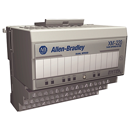
1440-SPD02-01RB:XM-220 双速模块
首选
1440-SPD02-01RB
速度测量模块
Serial #:
此产品尚未验证,请{}确认真实性
注册您的产品
生命周期状态:
活跃
产品概览
Description
1440-SPD02-01RB:XM-220 双速模块
概述
电气与连接
General Features
Electrical & Connectivity
功率和电气特性
继电器和控制输出
输入/输出 (I/O)
通信和接口
Technical Specifications
报警和故障管理
测量和参数
Compliance & Environment
标准与保护
物理特性
机械
结构
文档
下载
认证
替代产品
技术说明
| 唯一产品序列号 |
1440-SPD02-01RB
|
|---|---|
| 通用产品代码(UPC) |
781180505355
|
| 预计交期 |
129 天
|
| 标准保修期 |
1年 查看详情 |
| 原产国 |
美利坚合众国
|
| 状态指示灯 |
模块 - 红色/绿色,网络 - 红色/绿色,Channel 1 - 黄色/红色,Channel 2 - 黄色/红色,启动 - 黄色,继电器 - 红色,AUX - 预留以备将来使用
|
|---|---|
| 转速计输入 |
2
|
| 输出 |
2
|
| 非易失性组态 |
模块配置的副本保存在非易失性存储器中,配置在上电时从该存储器加载。保存在非易失性存储器中的配置只能通过串行接口发送的模块复位命令删除。
|
| 传感器 |
隔离型24V DC,用户可通过接线进行配置
|
|---|---|
| 接线类别 |
2 - 继电器和信号端口,3 - 串口和电源端口,2 - XM 总线端口
|
| 最大功耗 |
7W
|
| 模块 |
24V DC
|
| 消耗 |
最大300mA,典型值225mA
|
| 热产生 |
最大值为7W (24BTU/hr),典型值为4W (14BTU/hr)
|
| 电压和电流额定值 |
电源:24V DC@0.3A(最大),Class 2/SELV,继电器:120V AC@0.5A,110V DC@0.5A,30V DC@1.0A
|
| 电气连接类型 |
螺钉连接
|
| 线缆类型 |
信号连接:屏蔽,电源和继电器连接:非屏蔽
|
| 隔离电压 |
250V(连续),基本绝缘型,继电器与所有其他电路之间,其他电路之间未额定隔离,型式试验于1500V AC@60s
|
| 额定DC控制电源电压 |
24V
|
| 额定工作频率 |
0.0167kHz
|
| 驱动电压类型 |
DC
|
| 故障安全 |
通常通电(故障-安全),通常断电(非故障-安全)
|
|---|---|
| 数字 |
单个板载继电器,两个触点组 - DPDT(两个C型),与XM-441扩展继电器模块互连时可提供四个附加继电器,或四个可由远程控制系统或XM-440主继电器模块使用其状态的虚拟继电器
|
| 时间延迟 |
0~25.5s,可按100ms增量调节
|
| 板载继电器额定值 |
最大电压:120V DC @ 125V AC,电流:0~3.5A,最大功率:60W,62.5VA,最大电流在最高40°C (104°F) 时有效,然后降额至2A @ 65°C (149°F),机构额定值:120V AC @ 0.5A,110V DC @ 0.3A,30V DC @ 1.0A
|
| 激活已开启 |
报警状态:正常、警报、危险、解除报警、传感器故障、模块故障、转速计故障
|
| 逻辑 |
单个或成对的 AND 或 OR 逻辑,适用于任何报警
|
| 重置 |
模块顶部的本地复位开关、连接到端子座的远程复位开关、通过串口或 DeviceNet 接口的数字复位命令
|
| 锁存 |
锁存、非锁存
|
Input Signals
| 两个转速计输入 |
25V(最大峰间值50V),涡流传感器信号,磁性感应器,TTL输出设备
|
|---|---|
| 输入阻抗 |
最小120kΩ
|
| 速度测量误差 |
1~240rpm:0.2rpm,241~12000rpm:2rpm,12001~20400rpm:5rpm,20401~120000rpm:20rpm,120001~360000rpm:50rpm,360001~1200000rpm:160rpm
|
| 速度范围 |
1 r/m
|
Output Signals
| 4~20mA 输出 |
每个输出都可独立编程,用于表示任一通道的速度或加速。两个隔离输出,最大负载300Ω,每个输入通道一个有源缓冲器。
|
|---|---|
| 缓冲输出 |
通过接线可配置的输出范围,−24~9V、−5~24V、−5~9V,当模块配置为单冗余通道模式时,提供第三个缓冲输出,输出与有效输入信号相对应的CMOS(0~5V)电平方波
|
| DeviceNet网络 |
所有功能均采用标准 DeviceNet 协议(电源模块电源需独立提供),可用的 EDS 文件支持大多数符合 DeviceNet 的系统,通信速率由总线主站自动设置为125Kbps、250Kbps或500Kbps。
|
|---|---|
| 串行 |
通过迷你连接器或端子基本单元的 RS-232,通信速率固定为 19.2Kbps,通过串口组态工具进行本地配置
|
Alarms
| Operator |
大于、小于、在范围内、在范围外
|
|---|---|
| 报警参数 |
为以下各项分别提供的报警和危险对:速度、加速、零速度、转子锁定
|
| 滞后 |
用户可通过软件进行配置
|
Fault Management
| 涡流传感器 |
将偏置电压与故障限值进行比较
|
|---|---|
| 磁性拾音器 |
提供电流源,用于偏置无源磁性传感器,以检测开路或短路。
|
Measurement Modes & Configuration
| 单一冗余通道 |
一个传感器用于执行速度、加速和峰值速度测量。如果当前传感器发生故障,模块将自动切换到 s(冗余)传感器。
|
|---|---|
| 双通道 |
两个传感器独立使用,用于执行两个独立的速度、加速和峰值速度测量
|
| 反向旋转 |
两个传感器用于监测速度和方向。两个传感器必须不同相安装,以便通过监测轴键槽首先经过哪个传感器来确定旋转方向。
|
Measurement Types & Capabilities
| 单位 |
转速、旋转方向、加速(rpm/min)
|
|---|---|
| 峰间值速度捕捉 |
模块会保留自模块断电再上电以来所观察到的最高速度值,或保留手动重置后的峰间值速度。
|
| 测量参数 |
正向、反向、转速、旋转方向、加速(单位:rpm/min)
|
| EFT/B抗扰度 |
电源端口:2kV (5kHz),继电器和信号端口:1kV (5kHz),XM 总线端口:1kV (5kHz)
|
|---|---|
| 传导射频抗扰度 |
10V RMS,1kHz 正弦波,80% AM,频率范围 150kHz~80MHz
|
| 储存温度 |
−40°C
|
| 周围空气温度,最大 |
65°C
|
| 工作温度 |
−20°C
|
| 排放 |
A 类
|
| 敷形涂覆 |
所有印刷电路板均采用符合IPC-A-610C标准的敷形涂覆
|
| 浪涌瞬态抗扰度 |
2kV 线-地(CM),适用于继电器和屏蔽信号端口,2kV 线-地(CM),适用于 XM 总线端口
|
| 相对湿度 |
5~95% 无凝露
|
| 辐射射频抗扰度 |
10 V/m,1 kHz 正弦波 80% AM,频率范围 80...2000 MHz;10 V/m,200 Hz 50% 脉冲 100% AM,频率 900 MHz;10 V/m,200 Hz 50% 脉冲 100% AM,频率 1890 MHz;3 V/m,1 kHz 正弦波 80% AM,频率范围 2000...2700 MHz
|
| 防静电 |
6kV接触放电,8kV空气放电
|
| 非工作温度 |
−40°C
|
机械
| 冲击 |
Opsal:15G
|
|---|---|
| 功能转速监控 |
True
|
| 宽度 |
94mm
|
| 振动 |
2.0 G @ 10~500Hz
|
| 深度 |
94mm
|
| 高度 |
97mm
|
结构
| 外壳类型额定值 |
无(开放式)
|
|---|
提供下载
- XM Serial Configuration Utility R8
- Firmware for 1440-SPD02-01RB v8.018
- EDS files for 1440-SPD02-01RB (multi)
- EDS files for XM Family (multi)
截至 2026-07-17,此产品已获得上述多项认证。此日期前后销售的产品,所获认证可能有所不同。请查阅产品标签,确认具体产品所持有的相关认证。
正在查找认证文件?
请浏览我们内容详尽的资料库,查看该产品及其他产品的认证信息。
法规信息
| 欧盟进口商地址 |
Rockwell Automation N.V |
|---|---|
| 欧盟授权代表地址 |
Rockwell Automation N.V |
每页项目:
| 技术说明 |
|---|
概述
| 唯一产品序列号 |
1440-SPD02-01RB
|
|---|---|
| 通用产品代码(UPC) |
781180505355
|
| 预计交期 |
129 天
|
| 标准保修期 |
1年 查看详情 |
| 原产国 |
美利坚合众国
|
电气与连接
| 状态指示灯 |
模块 - 红色/绿色,网络 - 红色/绿色,Channel 1 - 黄色/红色,Channel 2 - 黄色/红色,启动 - 黄色,继电器 - 红色,AUX - 预留以备将来使用
|
|---|---|
| 转速计输入 |
2
|
| 输出 |
2
|
| 非易失性组态 |
模块配置的副本保存在非易失性存储器中,配置在上电时从该存储器加载。保存在非易失性存储器中的配置只能通过串行接口发送的模块复位命令删除。
|
Electrical & Connectivity
| 传感器 |
隔离型24V DC,用户可通过接线进行配置
|
|---|---|
| 接线类别 |
2 - 继电器和信号端口,3 - 串口和电源端口,2 - XM 总线端口
|
| 最大功耗 |
7W
|
| 模块 |
24V DC
|
| 消耗 |
最大300mA,典型值225mA
|
| 热产生 |
最大值为7W (24BTU/hr),典型值为4W (14BTU/hr)
|
| 电压和电流额定值 |
电源:24V DC@0.3A(最大),Class 2/SELV,继电器:120V AC@0.5A,110V DC@0.5A,30V DC@1.0A
|
| 电气连接类型 |
螺钉连接
|
| 线缆类型 |
信号连接:屏蔽,电源和继电器连接:非屏蔽
|
| 隔离电压 |
250V(连续),基本绝缘型,继电器与所有其他电路之间,其他电路之间未额定隔离,型式试验于1500V AC@60s
|
| 额定DC控制电源电压 |
24V
|
| 额定工作频率 |
0.0167kHz
|
| 驱动电压类型 |
DC
|
| 故障安全 |
通常通电(故障-安全),通常断电(非故障-安全)
|
|---|---|
| 数字 |
单个板载继电器,两个触点组 - DPDT(两个C型),与XM-441扩展继电器模块互连时可提供四个附加继电器,或四个可由远程控制系统或XM-440主继电器模块使用其状态的虚拟继电器
|
| 时间延迟 |
0~25.5s,可按100ms增量调节
|
| 板载继电器额定值 |
最大电压:120V DC @ 125V AC,电流:0~3.5A,最大功率:60W,62.5VA,最大电流在最高40°C (104°F) 时有效,然后降额至2A @ 65°C (149°F),机构额定值:120V AC @ 0.5A,110V DC @ 0.3A,30V DC @ 1.0A
|
| 激活已开启 |
报警状态:正常、警报、危险、解除报警、传感器故障、模块故障、转速计故障
|
| 逻辑 |
单个或成对的 AND 或 OR 逻辑,适用于任何报警
|
| 重置 |
模块顶部的本地复位开关、连接到端子座的远程复位开关、通过串口或 DeviceNet 接口的数字复位命令
|
| 锁存 |
锁存、非锁存
|
Input Signals
| 两个转速计输入 |
25V(最大峰间值50V),涡流传感器信号,磁性感应器,TTL输出设备
|
|---|---|
| 输入阻抗 |
最小120kΩ
|
| 速度测量误差 |
1~240rpm:0.2rpm,241~12000rpm:2rpm,12001~20400rpm:5rpm,20401~120000rpm:20rpm,120001~360000rpm:50rpm,360001~1200000rpm:160rpm
|
| 速度范围 |
1 r/m
|
Output Signals
| 4~20mA 输出 |
每个输出都可独立编程,用于表示任一通道的速度或加速。两个隔离输出,最大负载300Ω,每个输入通道一个有源缓冲器。
|
|---|---|
| 缓冲输出 |
通过接线可配置的输出范围,−24~9V、−5~24V、−5~9V,当模块配置为单冗余通道模式时,提供第三个缓冲输出,输出与有效输入信号相对应的CMOS(0~5V)电平方波
|
| DeviceNet网络 |
所有功能均采用标准 DeviceNet 协议(电源模块电源需独立提供),可用的 EDS 文件支持大多数符合 DeviceNet 的系统,通信速率由总线主站自动设置为125Kbps、250Kbps或500Kbps。
|
|---|---|
| 串行 |
通过迷你连接器或端子基本单元的 RS-232,通信速率固定为 19.2Kbps,通过串口组态工具进行本地配置
|
技术规格
Alarms
| Operator |
大于、小于、在范围内、在范围外
|
|---|---|
| 报警参数 |
为以下各项分别提供的报警和危险对:速度、加速、零速度、转子锁定
|
| 滞后 |
用户可通过软件进行配置
|
Fault Management
| 涡流传感器 |
将偏置电压与故障限值进行比较
|
|---|---|
| 磁性拾音器 |
提供电流源,用于偏置无源磁性传感器,以检测开路或短路。
|
Measurement Modes & Configuration
| 单一冗余通道 |
一个传感器用于执行速度、加速和峰值速度测量。如果当前传感器发生故障,模块将自动切换到 s(冗余)传感器。
|
|---|---|
| 双通道 |
两个传感器独立使用,用于执行两个独立的速度、加速和峰值速度测量
|
| 反向旋转 |
两个传感器用于监测速度和方向。两个传感器必须不同相安装,以便通过监测轴键槽首先经过哪个传感器来确定旋转方向。
|
Measurement Types & Capabilities
| 单位 |
转速、旋转方向、加速(rpm/min)
|
|---|---|
| 峰间值速度捕捉 |
模块会保留自模块断电再上电以来所观察到的最高速度值,或保留手动重置后的峰间值速度。
|
| 测量参数 |
正向、反向、转速、旋转方向、加速(单位:rpm/min)
|
Compliance & Environment
| EFT/B抗扰度 |
电源端口:2kV (5kHz),继电器和信号端口:1kV (5kHz),XM 总线端口:1kV (5kHz)
|
|---|---|
| 传导射频抗扰度 |
10V RMS,1kHz 正弦波,80% AM,频率范围 150kHz~80MHz
|
| 储存温度 |
−40°C
|
| 周围空气温度,最大 |
65°C
|
| 工作温度 |
−20°C
|
| 排放 |
A 类
|
| 敷形涂覆 |
所有印刷电路板均采用符合IPC-A-610C标准的敷形涂覆
|
| 浪涌瞬态抗扰度 |
2kV 线-地(CM),适用于继电器和屏蔽信号端口,2kV 线-地(CM),适用于 XM 总线端口
|
| 相对湿度 |
5~95% 无凝露
|
| 辐射射频抗扰度 |
10 V/m,1 kHz 正弦波 80% AM,频率范围 80...2000 MHz;10 V/m,200 Hz 50% 脉冲 100% AM,频率 900 MHz;10 V/m,200 Hz 50% 脉冲 100% AM,频率 1890 MHz;3 V/m,1 kHz 正弦波 80% AM,频率范围 2000...2700 MHz
|
| 防静电 |
6kV接触放电,8kV空气放电
|
| 非工作温度 |
−40°C
|
物理特性
机械
| 冲击 |
Opsal:15G
|
|---|---|
| 功能转速监控 |
True
|
| 宽度 |
94mm
|
| 振动 |
2.0 G @ 10~500Hz
|
| 深度 |
94mm
|
| 高度 |
97mm
|
结构
| 外壳类型额定值 |
无(开放式)
|
|---|
文档
|
产品简介
基本信息
-- |
|
1440-td001_-en-p
技术数据
1440-TD001 |
| 基本信息 | 出版 |
|---|---|
| 产品简介 | -- |
| 技术数据 | 出版 |
| 1440-td001_-en-p | 1440-TD001 |
下载
提供下载
- XM Serial Configuration Utility R8
- Firmware for 1440-SPD02-01RB v8.018
- EDS files for 1440-SPD02-01RB (multi)
- EDS files for XM Family (multi)
认证
截至 2026-07-17,此产品已获得上述多项认证。此日期前后销售的产品,所获认证可能有所不同。请查阅产品标签,确认具体产品所持有的相关认证。
正在查找认证文件?
请浏览我们内容详尽的资料库,查看该产品及其他产品的认证信息。
法规信息
| 欧盟进口商地址 |
Rockwell Automation N.V |
|---|---|
| 欧盟授权代表地址 |
Rockwell Automation N.V |
替代产品
每页项目:
技术说明
| 技术说明 |
|---|
基于制造地点的多个原产国
速度测量模块
1440-SPD02-01RB
关闭
打印
Copyright ©2026 Rockwell Automation, Inc.