| Accuracy | 0.20% |
|---|---|
| Alarm | True |
| Communications | EtherNet/IP and ControlNet |
| Frequency Rating | 40-75Hz |
| Interface | Webpage |
| Metering Voltage | 600VLL AC |
| Output | 4 Digital Relays |
| Vibration | 2 G |
|---|---|
| Shock | 50 G, nonoperating |
| Dielectric withstand | UL61010, EN61010 |
| Storage temperature | -40 to 85 °C |
| Operating temperature | -20 to 70 °C |
| Altitude | 2000 m, max |
| Installation location | Indoor use only |
| Humidity | 5...95% noncondensing |
| Height | 132 mm |
|---|---|
| Width | 185 mm |
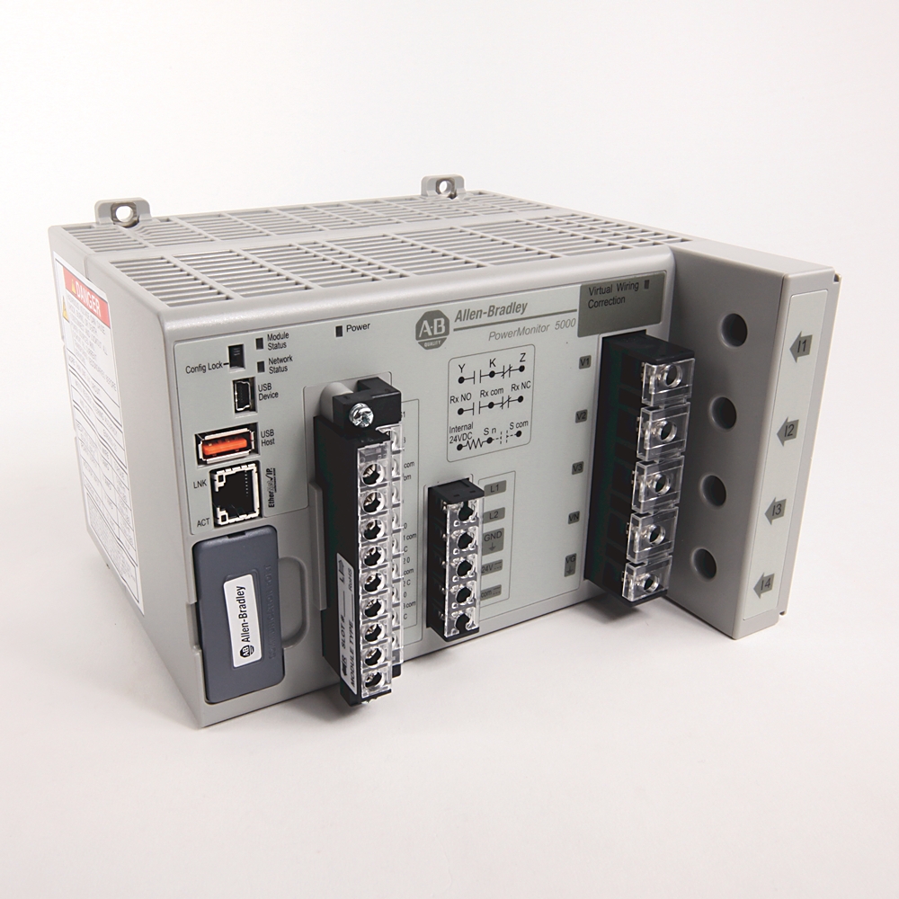
| Control power and ground wiring terminals | • 120...240V AC @ 50/60Hz, or 120...240V DC • 24V DC |
| Virtual wiring correction indicator | Indicates that a virtual wiring correction command has been applied to resolve wiring errors without rewiring |
| Voltage sensing wiring terminals | • Direct connect to up to 690V AC 3-phase line to line • Maximum nominal line to ground voltage 690 • Use potential transformers (PTs) for higher voltages • Neutral voltage and ground voltage connections |
| Device status indicators | • Device status - OFF: No control power - Flashing GREEN/RED: Self-test - Flashing GREEN: Power monitor has not been configured - GREEN: Power monitor is running - Flashing RED: Power monitor has detected a recoverable minor fault - RED: Power monitor has detected a non-recoverable major fault |
| Ethernet network port - standard RJ45 jack with status indicators | Ethernet port hardware is included on all models. These protocols and functions are supported: • EtherNet/IP™ network • HTML web page for configuration and data access Ethernet indicators • LNK indicator - Solid GREEN: IP link established - Off: No link established • ACT indicator - Flashing YELLOW: Data present on Ethernet port - Off: No data activity present |
| USB host port | USB standard A receptacle. Not used in this model. |
| Power | •Power status - OFF: no control power - GREEN: control power is present |
| Current sensing wiring terminals | Nominal input current 5 A, Use current transformers (CTs) to connect to power system |
| Configuration lock switch | When enabled, this switch helps prevent changes in configuration that can affect revenue accuracy. |
| USB device port | The USB device port is a USB Mini-B receptacle that accepts standard USB Mini-B plugs, for connection to a host device, such as a notebook computer. |
| Status input, KYZ output, and control relay wiring terminals | • Four internally powered (24V DC) status inputs • Status input 2 can be used for demand period synchronization • KYZ DPDT solid-state relay for signaling use • Three DPDT control relays |
| Network status indicators | • Network status (Native Ethernet port) - OFF: No control power - Flashing GREEN/RED: Self-test - Flashing GREEN: No CIP connection - Solid GREEN: CIP connection established - Flashing RED: CIP connection timed out - Solid RED: Duplicate IP address detected |
| Optional communication port | DeviceNet and ControlNet networks • Module status - OFF: No control power - Flashing GREEN/RED: Self-test - Flashing GREEN: Power monitor has not been configured - GREEN: Power monitor is running - Flashing RED: Power monitor has detected a recoverable minor fault - RED: Power monitor has detected a non-recoverable major fault • Network status - OFF: No control power - Flashing GREEN/RED: Self-test - Flashing GREEN: No CIP connection - Solid GREEN: CIP connection established - Flashing RED: CIP connection timed out - Solid RED: Duplicate address detected |
| IC rating class | UL 508, CSA 22.2 @ DC: Q300 |
|---|---|
| Resistive load switching | 10A @ 24V DC, maximum |
| Load switching | 100mA @ 5V AC, 50/60 Hz, RMS, minimum |
| Motor load switching | 1/3HP @ 125V AC, 50/60 Hz, RMS, maximum |
| Make values | (Inductive load) 30A @ 120V AC, 50/60 Hz, RMS, maximum |
| Break values | (Inductive load) 3A @ 120V AC, 50/60 Hz, RMS, maximum |
| Crest factor | V-V, V-N, and I, per phase: Yes |
|---|---|
| Reactive energy (kVARh) | True |
| Frequency | Nominal: 60 Hz |
| Real energy (kWh) | True |
| Reactive power (kVAR) | True |
| Real power (kW) | True |
| Apparent power (kVA) | True |
| Real power demand (kW) | True |
| Reactive power demand (kVAR) | True |
| Apparent power demand (kVA) | True |
| Demand power factor | True |
| Projected kW demand | True |
| Projected kVAR demand | True |
| Projected kVA demand | True |
| Voltage unbalance | True |
| Current unbalance | True |
| Voltage, L-L and L-N | True |
| Current per phase and total | True |
| Symmetrical component analysis | True |
| True power factor per phase and total | True |
| Displacement power factor per phase and total | True |
| Apparent energy (kVAh) | True |
| Demand, amps | True |
| Projected amps demand | True |
| EN 61000-4-30 10/12 cycle metering | True |
| Current consumption | True |
| Control power | 12VA @ 24V DC |
|---|---|
| Current sense inputs: I1, I2, I3 | Accuracy: ±0.1% @ 25°C 50/60 Hz unity power factor |
| Status inputs | True |
|---|---|
| Configurable via webpage | True |
| CIP energy object | True |
| Security | True |
| Wiring diagnostics | True |
| Virtual wiring correction | True |
| Network time synchronization | True |
| Network demand synchronization | True |
| IEEE 1588 precision time protocol | True |
| Pulse (digital) output (relay and KYZ) | True |
| Setpoint programming | True |
| Sag and swell detection | True |
| Web page | True |
| K-factor | True |
| Revenue accuracy | True |
| Total harmonic distortion (THD) | True |
| Waveform capture | True |
| Individual harmonics (DC-63rd) | True |
| Event synchronization | True |
| Individual harmonics (DC-127th) | True |
| Interharmonics | True |
| Transient detect | True |
| Flicker | True |
| Control power | 12VA @ 24V DC |
|---|---|
| Current sense inputs: I1, I2, I3 | Accuracy: ±0.1% @ 25°C 50/60 Hz unity power factor |
| Power functions | • ANSI C12.20 -2010 class 0.2 clause 5.5.4 • EN 62053-22 -2003 class 0.2 accuracy clause 8 |
|---|---|
| Demand functions | • ANSI C12.20 -2010 class 0.2 clause 5.5.4 • EN 62053-22 -2003 class 0.2 accuracy clause 8 |
| Metering update rates | One update per line cycle, 1024 sAles per cycle per channel |
| VG | Connect to power system earth ground only, This connection is a functional ground. |
| Energy functions | • ANSI C12.20 -2010 class 0.2 clause 5.5.4 • EN 62053-22 -2003 class 0.2 accuracy clause 8 |
| Description | PowerMonitor 5000 M8 unit with native ethernet and optional controlnet network communication |
|---|---|
| Ampere meter | True |
| Blind power meter | True |
| Frequency meter | True |
| Pulse counter | True |
| Voltmeter | True |
| Effective power measurement device | True |
| Depth | 178 mm |
|---|
| Time of use log | True |
|---|---|
| Energy log | True |
| Minimum/maximum log | True |
| Load factor log | True |
| Alarm log | True |
| Data log | True |
| Event log | True |
| Setpoint log | True |
| Power quality log | True |
| Waveform log | True |
| Trigger data log | True |
| Snapshot Log | True |
| Waveform synchronization broadcast (WSB) | True |
| Logical setpoint programming | True |
| EN 50160 weekly log | True |
| EN 50160 yearly log | True |
| EtherNet/IP | True |
|---|---|
| ControlNet | True |
| 图纸 | |
|---|---|
| 3 DImensional Drawing (PDF) | Download (PDF) |
| 2D Drawing (PDF) | Download (PDF) |
| 3D STEP Model (STP) | Download (ZIP) |
| Product Drawing | Drawing (DXF) |
| 图纸 |
|---|
| 3 DImensional Drawing (PDF) Download (PDF) |
| 2D Drawing (PDF) Download (PDF) |
| 3D STEP Model (STP) Download (ZIP) |
| Product Drawing Drawing (DXF) |
登录您的罗克韦尔自动化帐户以查看和下载技术图纸.
登录
| 类型 | 资源 | 出版 |
|---|---|---|
| General | PowerMonitor 5000 Product Profile | 1426-PP001 |
| General | Product Cutsheet | -- |
| General | PowerMonitor 5000 USB Driver Installation and Configuration Instructions | 1426-IN001 |
| User Manual | 1426-um001_-en-p | 1426-UM001 |
- Australian RCM
This product was certified with the above certifications as of 2025-09-09. Products sold before or after this date might carry different certifications. Please review the product label to check for the certifications your specific product carries.
技术规格
| Accuracy | 0.20% |
|---|---|
| Alarm | True |
| Communications | EtherNet/IP and ControlNet |
| Frequency Rating | 40-75Hz |
| Interface | Webpage |
| Metering Voltage | 600VLL AC |
| Output | 4 Digital Relays |
| Vibration | 2 G |
|---|---|
| Shock | 50 G, nonoperating |
| Dielectric withstand | UL61010, EN61010 |
| Storage temperature | -40 to 85 °C |
| Operating temperature | -20 to 70 °C |
| Altitude | 2000 m, max |
| Installation location | Indoor use only |
| Humidity | 5...95% noncondensing |
| Height | 132 mm |
|---|---|
| Width | 185 mm |
| Control power and ground wiring terminals | • 120...240V AC @ 50/60Hz, or 120...240V DC • 24V DC |
| Virtual wiring correction indicator | Indicates that a virtual wiring correction command has been applied to resolve wiring errors without rewiring |
| Voltage sensing wiring terminals | • Direct connect to up to 690V AC 3-phase line to line • Maximum nominal line to ground voltage 690 • Use potential transformers (PTs) for higher voltages • Neutral voltage and ground voltage connections |
| Device status indicators | • Device status - OFF: No control power - Flashing GREEN/RED: Self-test - Flashing GREEN: Power monitor has not been configured - GREEN: Power monitor is running - Flashing RED: Power monitor has detected a recoverable minor fault - RED: Power monitor has detected a non-recoverable major fault |
| Ethernet network port - standard RJ45 jack with status indicators | Ethernet port hardware is included on all models. These protocols and functions are supported: • EtherNet/IP™ network • HTML web page for configuration and data access Ethernet indicators • LNK indicator - Solid GREEN: IP link established - Off: No link established • ACT indicator - Flashing YELLOW: Data present on Ethernet port - Off: No data activity present |
| USB host port | USB standard A receptacle. Not used in this model. |
| Power | •Power status - OFF: no control power - GREEN: control power is present |
| Current sensing wiring terminals | Nominal input current 5 A, Use current transformers (CTs) to connect to power system |
| Configuration lock switch | When enabled, this switch helps prevent changes in configuration that can affect revenue accuracy. |
| USB device port | The USB device port is a USB Mini-B receptacle that accepts standard USB Mini-B plugs, for connection to a host device, such as a notebook computer. |
| Status input, KYZ output, and control relay wiring terminals | • Four internally powered (24V DC) status inputs • Status input 2 can be used for demand period synchronization • KYZ DPDT solid-state relay for signaling use • Three DPDT control relays |
| Network status indicators | • Network status (Native Ethernet port) - OFF: No control power - Flashing GREEN/RED: Self-test - Flashing GREEN: No CIP connection - Solid GREEN: CIP connection established - Flashing RED: CIP connection timed out - Solid RED: Duplicate IP address detected |
| Optional communication port | DeviceNet and ControlNet networks • Module status - OFF: No control power - Flashing GREEN/RED: Self-test - Flashing GREEN: Power monitor has not been configured - GREEN: Power monitor is running - Flashing RED: Power monitor has detected a recoverable minor fault - RED: Power monitor has detected a non-recoverable major fault • Network status - OFF: No control power - Flashing GREEN/RED: Self-test - Flashing GREEN: No CIP connection - Solid GREEN: CIP connection established - Flashing RED: CIP connection timed out - Solid RED: Duplicate address detected |
| IC rating class | UL 508, CSA 22.2 @ DC: Q300 |
|---|---|
| Resistive load switching | 10A @ 24V DC, maximum |
| Load switching | 100mA @ 5V AC, 50/60 Hz, RMS, minimum |
| Motor load switching | 1/3HP @ 125V AC, 50/60 Hz, RMS, maximum |
| Make values | (Inductive load) 30A @ 120V AC, 50/60 Hz, RMS, maximum |
| Break values | (Inductive load) 3A @ 120V AC, 50/60 Hz, RMS, maximum |
| Crest factor | V-V, V-N, and I, per phase: Yes |
|---|---|
| Reactive energy (kVARh) | True |
| Frequency | Nominal: 60 Hz |
| Real energy (kWh) | True |
| Reactive power (kVAR) | True |
| Real power (kW) | True |
| Apparent power (kVA) | True |
| Real power demand (kW) | True |
| Reactive power demand (kVAR) | True |
| Apparent power demand (kVA) | True |
| Demand power factor | True |
| Projected kW demand | True |
| Projected kVAR demand | True |
| Projected kVA demand | True |
| Voltage unbalance | True |
| Current unbalance | True |
| Voltage, L-L and L-N | True |
| Current per phase and total | True |
| Symmetrical component analysis | True |
| True power factor per phase and total | True |
| Displacement power factor per phase and total | True |
| Apparent energy (kVAh) | True |
| Demand, amps | True |
| Projected amps demand | True |
| EN 61000-4-30 10/12 cycle metering | True |
| Current consumption | True |
| Control power | 12VA @ 24V DC |
|---|---|
| Current sense inputs: I1, I2, I3 | Accuracy: ±0.1% @ 25°C 50/60 Hz unity power factor |
| Status inputs | True |
|---|---|
| Configurable via webpage | True |
| CIP energy object | True |
| Security | True |
| Wiring diagnostics | True |
| Virtual wiring correction | True |
| Network time synchronization | True |
| Network demand synchronization | True |
| IEEE 1588 precision time protocol | True |
| Pulse (digital) output (relay and KYZ) | True |
| Setpoint programming | True |
| Sag and swell detection | True |
| Web page | True |
| K-factor | True |
| Revenue accuracy | True |
| Total harmonic distortion (THD) | True |
| Waveform capture | True |
| Individual harmonics (DC-63rd) | True |
| Event synchronization | True |
| Individual harmonics (DC-127th) | True |
| Interharmonics | True |
| Transient detect | True |
| Flicker | True |
| Control power | 12VA @ 24V DC |
|---|---|
| Current sense inputs: I1, I2, I3 | Accuracy: ±0.1% @ 25°C 50/60 Hz unity power factor |
| Power functions | • ANSI C12.20 -2010 class 0.2 clause 5.5.4 • EN 62053-22 -2003 class 0.2 accuracy clause 8 |
|---|---|
| Demand functions | • ANSI C12.20 -2010 class 0.2 clause 5.5.4 • EN 62053-22 -2003 class 0.2 accuracy clause 8 |
| Metering update rates | One update per line cycle, 1024 sAles per cycle per channel |
| VG | Connect to power system earth ground only, This connection is a functional ground. |
| Energy functions | • ANSI C12.20 -2010 class 0.2 clause 5.5.4 • EN 62053-22 -2003 class 0.2 accuracy clause 8 |
| Description | PowerMonitor 5000 M8 unit with native ethernet and optional controlnet network communication |
|---|---|
| Ampere meter | True |
| Blind power meter | True |
| Frequency meter | True |
| Pulse counter | True |
| Voltmeter | True |
| Effective power measurement device | True |
| Depth | 178 mm |
|---|
| Time of use log | True |
|---|---|
| Energy log | True |
| Minimum/maximum log | True |
| Load factor log | True |
| Alarm log | True |
| Data log | True |
| Event log | True |
| Setpoint log | True |
| Power quality log | True |
| Waveform log | True |
| Trigger data log | True |
| Snapshot Log | True |
| Waveform synchronization broadcast (WSB) | True |
| Logical setpoint programming | True |
| EN 50160 weekly log | True |
| EN 50160 yearly log | True |
| EtherNet/IP | True |
|---|---|
| ControlNet | True |
图纸
| 图纸 | |
|---|---|
| 3 DImensional Drawing (PDF) | Download (PDF) |
| 2D Drawing (PDF) | Download (PDF) |
| 3D STEP Model (STP) | Download (ZIP) |
| Product Drawing | Drawing (DXF) |
| 图纸 |
|---|
| 3 DImensional Drawing (PDF) Download (PDF) |
| 2D Drawing (PDF) Download (PDF) |
| 3D STEP Model (STP) Download (ZIP) |
| Product Drawing Drawing (DXF) |
登录您的罗克韦尔自动化帐户以查看和下载技术图纸.
登录
文档
|
PowerMonitor 5000 Product Profile
General
1426-PP001 |
|
Product Cutsheet
General
-- |
|
PowerMonitor 5000 USB Driver Installation and Configuration Instructions
General
1426-IN001 |
|
1426-um001_-en-p
User Manual
1426-UM001 |
| 类型 | 资源 | 出版 |
|---|---|---|
| General | PowerMonitor 5000 Product Profile | 1426-PP001 |
| General | Product Cutsheet | -- |
| General | PowerMonitor 5000 USB Driver Installation and Configuration Instructions | 1426-IN001 |
| User Manual | 1426-um001_-en-p | 1426-UM001 |
认证
- Australian RCM
This product was certified with the above certifications as of 2025-09-09. Products sold before or after this date might carry different certifications. Please review the product label to check for the certifications your specific product carries.
配件
技术说明
Loading
Copyright ©2025 Rockwell Automation, Inc.