View all 1426 PowerMonitor 5000
首选
,
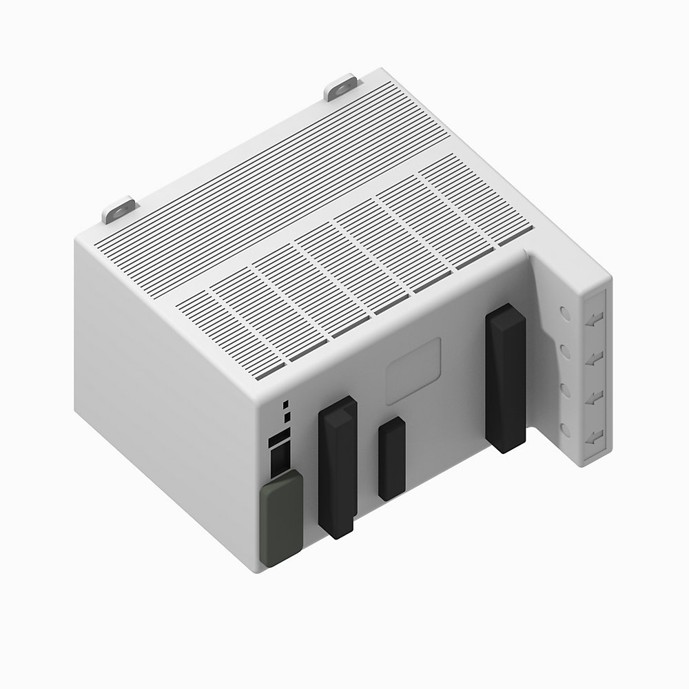
1426-M5E
Powermonitor 5000 基础质量计
Serial #:
This product has not been verified. Please register your product to confirm authenticity.
生命周期状态:
活跃
产品概览
产品注册
生命周期状态:
活跃
产品概览
产品注册
技术规格
基本信息
Environmental Specifications
Hardware Features
Control Relay
Measured Parameters
Input/output specifications
Other Functions
Input/Output Specifications
General specifications
Electrical
Dimension
Logging Functions
Communication
图纸
文档
认证
配件
技术说明
| 准确性 |
0.20%
|
|---|---|
| 报警 |
Yes
|
| 应用 |
Power Management/Quality m
|
| 通信 |
EtherNet/IP
|
| 频率额定值 |
40~75Hz
|
| 接口 |
网页
|
| 测量电压 |
600VLL AC
|
| 输出 |
4个数字继电器
|
| 振动 |
2 G
|
|---|---|
| 冲击 |
50G,非工作状态
|
| 介电耐受性 |
UL61010、EN61010
|
| 储存温度 |
−40~85°C
|
| 工作温度 |
−20~70°C
|
| 海拔高度 |
最大2000m
|
| 安装位置 |
仅限室内使用
|
| 湿度 |
5~95% 无凝露
|
| 高度 |
132mm
|
|---|---|
| 宽度 |
185mm
|
| 控制电源和接地接线端子 |
• 120~240V AC @ 50/60Hz,或 120~240V DC • 24V DC
|
| 虚拟接线校正指示器 |
使用电流互感器(CT)连接到电力系统
|
| 电压检测接线端子 |
• 直接连接至最高690V AC三相线间电压
• 最大标称线对地电压690V
• 对于更高电压,使用电压互感器(PT)
• 中性点电压和接地电压连接
|
| 设备状态指示器 |
• 设备状态
- 关闭:无控制电源
- 绿色/红色闪烁:自检
- 绿色闪烁:电源监视器未配置
- 绿色:电源监视器正在运行
- 红色闪烁:电源监视器检测到可恢复的次要故障
- 红色:电源监视器检测到不可恢复的主要故障
|
| 以太网网络端口-带状态指示灯的标准RJ45插孔 |
所有型号均配备以太网端口硬件。支持以下协议和功能: • EtherNet/IP™ 网络 • 用于配置和数据访问的 HTML 网页 以太网指示灯 • LNK 指示灯 - 绿色常亮:IP 链路已建立 - 熄灭:未建立链路 • ACT 指示灯 - 黄色闪烁:以太网端口上有数据 - 熄灭:无数据活动
|
| USB 主机端口 |
USB 标准 A 型插座。本型号未使用。
|
| 电源 |
•电源状态 - OFF:无控制电源 - GREEN:有控制电源
|
| 电流检测接线端子 |
标称输入电流5A,使用电流互感器 (CT) 连接到电力系统
|
| 配置锁定开关 |
启用后,该开关有助于防止可能影响收入准确性的配置更改。
|
| USB 设备通信端口 |
USB 设备端口是一个 USB Mini-B 插座,可接受标准 USB Mini-B 插头,用于连接到主机设备,例如笔记本电脑。
|
| 状态输入、KYZ 输出和控制继电器接线端子 |
• 四个内部供电(24V DC)状态输入
• 状态输入 2 可用于需求周期同步
• 用于信号传送的 KYZ DPDT 固态型继电器
• 三个 DPDT 控制继电器
|
| 网络状态指示器 |
• 网络状态(本地以太网端口) - 关闭:无控制电源 - 绿色/红色闪烁:自检 - 绿色闪烁:无 CIP 连接 - 绿色常亮:已建立 CIP 连接 - 红色闪烁:CIP 连接超时 - 红色常亮:检测到 IP 地址重复
|
| IC 额定等级 |
UL 508、CSA 22.2 @ DC: Q300
|
|---|---|
| 阻性负载切换 |
10A @ 24V DC,最大
|
| 负载切换 |
100mA @ 5V AC,50/60Hz,RMS,最小值
|
| 电机负载切换 |
1/3HP @ 125V AC,50/60Hz,RMS,最大值
|
| 制定数值 |
(感性负载)30A@120V AC,50/60Hz,RMS,最大
|
| 断点值 |
(感性负载)0.55A@125V DC,最大
|
| 峰值因数 |
每相 V-V、V-N 和 I:Yes
|
|---|---|
| 无功电能 (kVARh) |
Yes
|
| 频率 |
标称值:60Hz
|
| 有功电能 (kWh) |
Yes
|
| 无功功率 (kVAR) |
Yes
|
| 有功功率 (kW) |
Yes
|
| 视在功率 (kVA) |
Yes
|
| 有功功率需求 (kW) |
Yes
|
| 无功功率需求 (kvar) |
Yes
|
| 视在功率需求 (kVA) |
Yes
|
| 需量功率因数 |
Yes
|
| 预计kW需求 |
Yes
|
| 预计kVAR需求 |
Yes
|
| 预计kVA需求 |
Yes
|
| 电压不平衡 |
Yes
|
| 电流不平衡 |
Yes
|
| 电压,L-L 和 L-N |
Yes
|
| 每相电流与总电流 |
Yes
|
| 对称分量分析 |
Yes
|
| 每相和总的有功功率因数 |
Yes
|
| 每相及总位移功率因数 |
Yes
|
| 视在能量 (kVAh) |
Yes
|
| 需求,A |
Yes
|
| 预计电流需求 |
Yes
|
| 电流消耗 |
Yes
|
| 控制电源 |
12VA @ 24V DC
|
|---|---|
| 电流检测输入:I₁、I₂、I₃ |
精度:0.1%(25°C,50/60Hz,功率因数为1)
|
| 状态输入 |
Yes
|
|---|---|
| 可通过网页配置 |
Yes
|
| CIP 能量对象 |
Yes
|
| 安全性 |
Yes
|
| 接线诊断 |
Yes
|
| 虚拟接线修正 |
Yes
|
| 网络时间同步 |
Yes
|
| 网络需求同步 |
Yes
|
| IEEE 1588 精密时间同步协议 |
Yes
|
| 脉冲(数字)输出(继电器和 KYZ) |
Yes
|
| 设定值编程 |
Yes
|
| 电压骤降和骤升检测 |
Yes
|
| 网页 |
Yes
|
| K 系数 |
Yes
|
| 收入准确度 |
Yes
|
| 总谐波失真(THD) |
Yes
|
| 控制电源 |
12VA @ 24V DC
|
|---|---|
| 电流检测输入:I₁、I₂、I₃ |
精度:0.1%(25°C,50/60Hz,功率因数为1)
|
| 电源功能 |
• ANSI C12.20 -2010 0.2 类第 5.5.4 条款 • EN 62053-22 -2003 0.2 类准确度第 8 条款
|
|---|---|
| 需求函数 |
• ANSI C12.20 -2010 0.2 类第 5.5.4 条款 • EN 62053-22 -2003 0.2 类准确度第 8 条款
|
| 计量更新速率 |
每个周期更新一次,每个通道每个周期有1024次采样
|
| VG |
仅连接到电源系统地线,该连接为功能性接地。
|
| 能量功能 |
• ANSI C12.20 -2010 0.2 类第 5.5.4 条款 • EN 62053-22 -2003 0.2 类准确度第 8 条款
|
| 描述 |
带原生以太网通信网络的 PowerMonitor 5000 M5 单元
|
|---|---|
| 安培表 |
Yes
|
| 无功率表 |
Yes
|
| 频率计 |
Yes
|
| 脉冲计数器 |
Yes
|
| 电压表 |
Yes
|
| 有效功率测量设备 |
Yes
|
| 深度 |
178mm
|
|---|
| 使用时间日志 |
Yes
|
|---|---|
| 能量日志 |
Yes
|
| 最小/最大日志 |
Yes
|
| 负载系数日志 |
Yes
|
| 报警日志 |
Yes
|
| 数据日志 |
Yes
|
| 事件日志 |
Yes
|
| 设定值日志 |
Yes
|
| EtherNet/IP |
Yes
|
|---|
| 基本信息 | 出版 |
|---|---|
| 产品简介 | -- |
| PowerMonitor 5000 产品简介 | 1426-PP001 |
| PowerMonitor 5000 USB 驱动程序安装和配置说明 | 1426-IN001 |
| 用户手册 | 出版 |
|---|---|
| 1426-um001_-zh-p | 1426-UM001 |
- 澳大利亚RCM
截至 2026-04-07,此产品已获得上述多项认证。此日期前后销售的产品,所获认证可能有所不同。请查阅产品标签,确认具体产品所持有的相关认证。
每页项目:
| 技术说明 |
|---|
技术规格
| 准确性 |
0.20%
|
|---|---|
| 报警 |
Yes
|
| 应用 |
Power Management/Quality m
|
| 通信 |
EtherNet/IP
|
| 频率额定值 |
40~75Hz
|
| 接口 |
网页
|
| 测量电压 |
600VLL AC
|
| 输出 |
4个数字继电器
|
| 振动 |
2 G
|
|---|---|
| 冲击 |
50G,非工作状态
|
| 介电耐受性 |
UL61010、EN61010
|
| 储存温度 |
−40~85°C
|
| 工作温度 |
−20~70°C
|
| 海拔高度 |
最大2000m
|
| 安装位置 |
仅限室内使用
|
| 湿度 |
5~95% 无凝露
|
| 高度 |
132mm
|
|---|---|
| 宽度 |
185mm
|
| 控制电源和接地接线端子 |
• 120~240V AC @ 50/60Hz,或 120~240V DC • 24V DC
|
| 虚拟接线校正指示器 |
使用电流互感器(CT)连接到电力系统
|
| 电压检测接线端子 |
• 直接连接至最高690V AC三相线间电压
• 最大标称线对地电压690V
• 对于更高电压,使用电压互感器(PT)
• 中性点电压和接地电压连接
|
| 设备状态指示器 |
• 设备状态
- 关闭:无控制电源
- 绿色/红色闪烁:自检
- 绿色闪烁:电源监视器未配置
- 绿色:电源监视器正在运行
- 红色闪烁:电源监视器检测到可恢复的次要故障
- 红色:电源监视器检测到不可恢复的主要故障
|
| 以太网网络端口-带状态指示灯的标准RJ45插孔 |
所有型号均配备以太网端口硬件。支持以下协议和功能: • EtherNet/IP™ 网络 • 用于配置和数据访问的 HTML 网页 以太网指示灯 • LNK 指示灯 - 绿色常亮:IP 链路已建立 - 熄灭:未建立链路 • ACT 指示灯 - 黄色闪烁:以太网端口上有数据 - 熄灭:无数据活动
|
| USB 主机端口 |
USB 标准 A 型插座。本型号未使用。
|
| 电源 |
•电源状态 - OFF:无控制电源 - GREEN:有控制电源
|
| 电流检测接线端子 |
标称输入电流5A,使用电流互感器 (CT) 连接到电力系统
|
| 配置锁定开关 |
启用后,该开关有助于防止可能影响收入准确性的配置更改。
|
| USB 设备通信端口 |
USB 设备端口是一个 USB Mini-B 插座,可接受标准 USB Mini-B 插头,用于连接到主机设备,例如笔记本电脑。
|
| 状态输入、KYZ 输出和控制继电器接线端子 |
• 四个内部供电(24V DC)状态输入
• 状态输入 2 可用于需求周期同步
• 用于信号传送的 KYZ DPDT 固态型继电器
• 三个 DPDT 控制继电器
|
| 网络状态指示器 |
• 网络状态(本地以太网端口) - 关闭:无控制电源 - 绿色/红色闪烁:自检 - 绿色闪烁:无 CIP 连接 - 绿色常亮:已建立 CIP 连接 - 红色闪烁:CIP 连接超时 - 红色常亮:检测到 IP 地址重复
|
| IC 额定等级 |
UL 508、CSA 22.2 @ DC: Q300
|
|---|---|
| 阻性负载切换 |
10A @ 24V DC,最大
|
| 负载切换 |
100mA @ 5V AC,50/60Hz,RMS,最小值
|
| 电机负载切换 |
1/3HP @ 125V AC,50/60Hz,RMS,最大值
|
| 制定数值 |
(感性负载)30A@120V AC,50/60Hz,RMS,最大
|
| 断点值 |
(感性负载)0.55A@125V DC,最大
|
| 峰值因数 |
每相 V-V、V-N 和 I:Yes
|
|---|---|
| 无功电能 (kVARh) |
Yes
|
| 频率 |
标称值:60Hz
|
| 有功电能 (kWh) |
Yes
|
| 无功功率 (kVAR) |
Yes
|
| 有功功率 (kW) |
Yes
|
| 视在功率 (kVA) |
Yes
|
| 有功功率需求 (kW) |
Yes
|
| 无功功率需求 (kvar) |
Yes
|
| 视在功率需求 (kVA) |
Yes
|
| 需量功率因数 |
Yes
|
| 预计kW需求 |
Yes
|
| 预计kVAR需求 |
Yes
|
| 预计kVA需求 |
Yes
|
| 电压不平衡 |
Yes
|
| 电流不平衡 |
Yes
|
| 电压,L-L 和 L-N |
Yes
|
| 每相电流与总电流 |
Yes
|
| 对称分量分析 |
Yes
|
| 每相和总的有功功率因数 |
Yes
|
| 每相及总位移功率因数 |
Yes
|
| 视在能量 (kVAh) |
Yes
|
| 需求,A |
Yes
|
| 预计电流需求 |
Yes
|
| 电流消耗 |
Yes
|
| 控制电源 |
12VA @ 24V DC
|
|---|---|
| 电流检测输入:I₁、I₂、I₃ |
精度:0.1%(25°C,50/60Hz,功率因数为1)
|
| 状态输入 |
Yes
|
|---|---|
| 可通过网页配置 |
Yes
|
| CIP 能量对象 |
Yes
|
| 安全性 |
Yes
|
| 接线诊断 |
Yes
|
| 虚拟接线修正 |
Yes
|
| 网络时间同步 |
Yes
|
| 网络需求同步 |
Yes
|
| IEEE 1588 精密时间同步协议 |
Yes
|
| 脉冲(数字)输出(继电器和 KYZ) |
Yes
|
| 设定值编程 |
Yes
|
| 电压骤降和骤升检测 |
Yes
|
| 网页 |
Yes
|
| K 系数 |
Yes
|
| 收入准确度 |
Yes
|
| 总谐波失真(THD) |
Yes
|
| 控制电源 |
12VA @ 24V DC
|
|---|---|
| 电流检测输入:I₁、I₂、I₃ |
精度:0.1%(25°C,50/60Hz,功率因数为1)
|
| 电源功能 |
• ANSI C12.20 -2010 0.2 类第 5.5.4 条款 • EN 62053-22 -2003 0.2 类准确度第 8 条款
|
|---|---|
| 需求函数 |
• ANSI C12.20 -2010 0.2 类第 5.5.4 条款 • EN 62053-22 -2003 0.2 类准确度第 8 条款
|
| 计量更新速率 |
每个周期更新一次,每个通道每个周期有1024次采样
|
| VG |
仅连接到电源系统地线,该连接为功能性接地。
|
| 能量功能 |
• ANSI C12.20 -2010 0.2 类第 5.5.4 条款 • EN 62053-22 -2003 0.2 类准确度第 8 条款
|
| 描述 |
带原生以太网通信网络的 PowerMonitor 5000 M5 单元
|
|---|---|
| 安培表 |
Yes
|
| 无功率表 |
Yes
|
| 频率计 |
Yes
|
| 脉冲计数器 |
Yes
|
| 电压表 |
Yes
|
| 有效功率测量设备 |
Yes
|
| 深度 |
178mm
|
|---|
| 使用时间日志 |
Yes
|
|---|---|
| 能量日志 |
Yes
|
| 最小/最大日志 |
Yes
|
| 负载系数日志 |
Yes
|
| 报警日志 |
Yes
|
| 数据日志 |
Yes
|
| 事件日志 |
Yes
|
| 设定值日志 |
Yes
|
| EtherNet/IP |
Yes
|
|---|
图纸
文档
|
产品简介
基本信息
-- |
|
PowerMonitor 5000 产品简介
基本信息
1426-PP001 |
|
PowerMonitor 5000 USB 驱动程序安装和配置说明
基本信息
1426-IN001 |
|
1426-um001_-zh-p
用户手册
1426-UM001 |
| 基本信息 | 出版 |
|---|---|
| 产品简介 | -- |
| PowerMonitor 5000 产品简介 | 1426-PP001 |
| PowerMonitor 5000 USB 驱动程序安装和配置说明 | 1426-IN001 |
| 用户手册 | 出版 |
| 1426-um001_-zh-p | 1426-UM001 |
认证
- 澳大利亚RCM
截至 2026-04-07,此产品已获得上述多项认证。此日期前后销售的产品,所获认证可能有所不同。请查阅产品标签,确认具体产品所持有的相关认证。
配件
每页项目:
技术说明
| 技术说明 |
|---|
Powermonitor 5000 基础质量计
1426-M5E
关闭
打印
Copyright ©2026 Rockwell Automation, Inc.
本网站上的内容已使用为人工智能 (AI) 翻译,未经人工审核或编辑。内容可能包含错误或不准确之处,并按“原样”提供,不提供任何形式的担保。英文版本内容为正式文本是内容的英文版本。