| Auxiliary Contact Cnfg | 1 NO / 5 NC |
|---|---|
| Coil Code | 24V50/60Hz/24V DC Elec Cl |
| Maximum Ampere Rating | 16 A |
| Voltage type for actuating | DC |
|---|---|
| Rated control supply voltage at AC 50 Hz | 0 V |
| Rated control supply voltage at AC 60 Hz | 0 V |
| Rated control supply voltage at DC | 24 V |
| Current (Ie), max | 16 A |
| Switching frequency, max | 220 ops/h |
| Main current circuit resistance | 2.7 mohm |
| Cross section per UL/CSA | 16 |
| Rated operational current for contactor at elevator duty (UL/CSA) | 5Hp @ 230V |
| Rated isolation voltage (Ui) | 690V @ IEC |
| Rated voltage (Ue) | 690V @ AC, 50/60 Hz |
| Rated operational power for contactor at wye-delta | 7.5Hp @ 200V, 60 Hz |
| Rated filament current | 18A @ 230/240V, AC-5b |
| Power dissipation | 2.1 W @ 400V, AC-3, Ie |
| Coil terminal conductor cross section | 1...4 mm² @ 2 conductor |
| Rated current (enclosed) | 17.5A @ 200V, 3-phase per UL/CSA |
| Rated power (enclosed) | 5Hp @ 230V, 3-phase per UL/CSA |
| Coil consumption pick-up (avg/peak) | 14/22 W @ DC (electronic-EA) |
| General purpose current (enclosed) | 30 A per UL/CSA |
| Capacitance, max | 500 µF @ short-circuit current of 20 kA |
| Switching of low inductive loads | 32A @ 440V, AC-7a per IEC 61095 (50 Hz) |
| Operating limits, pick-up | (0.85...1.1) x Us @ 50 Hz, 60 Hz, 50/60 Hz |
| Switching of motor load | 19A @ 230V, AC-7b per IEC 61095 (50 Hz) |
| Short time withstand (Icw) | 170A @ 10s, 60 °C |
| Coil consumption, hold-in | 9.5VA/2.7 W @ 50 Hz, 60 Hz, 50/60 Hz |
| Coil consumption, pick-up | 75VA @ 50 Hz, 60 Hz, 50/60 Hz |
| Operating time | 20...50 ms @ DC (electronic) opening delay |
| Total power dissipation | DC control (electronic): 3.8 W @ 400V, AC-3, Ie |
| Operating limits, dropout | (0.3...0.6) x Us @ 50 Hz, 60 Hz, 50/60 Hz |
| Switching of lamps | Gas discharge lA, open: 28A @ 40°C, AC-5a |
| Switching of hermetically sealed cooling compressor motors | 9.3A @ 690V, AC-8b (manual reset of overload release (50 Hz)) |
| Coil insulation class | Class F per IEC 60085, UL Class 105 |
| Rating for switching AC motors | 7.5 kW @ 690V @ 50Hz, 3-phase (AC-2, AC-3, AC-4) |
| BS88 fuses current rating | Type 2 (per IEC 60947-4-1): 32A @ 415V, 65 kA available fault current |
| UL class K5 and RK5 fuses rating | 70A @ 600V, 5 kA available fault current per UL 508 and CSA 22.2 No. 14 |
| UL class CC and CSA HRCI-MISC fuses rating | 30A @ 100kA available fault current per UL 508 and CSA 22.2 No. 14 |
| UL inverse-time circuit breaker | 50A @ 480V, 5 kA available fault current per UL 508 and CSA 22.2 No. 14 |
| Coil voltage | 24V DC electronic coil |
| Rated operational current (Ie) | 9A @ 690V, AC-4 (approximately 200000 ops) |
| Rated operational power (Pe) | 7.5 kW @ 690V, AC-4 (approximately 200000 ops) |
| DIN fuses (gG, gL) current rating | Type 2 (per IEC 60947-4-1): 35A @ 690V, 50 kA available fault current |
| UL class J and CSA HRCI-J fuses rating | 30A @ 100kA available fault current per UL 508 and CSA 22.2 No. 14 |
| Switching of power transformers | Apparent power: 9.4 kVA @ 500V, AC-6a @ 50Hz (n = 30) |
| Switching of 3-phase Capacitors | Single capacitor: 8.5 kVAR @ 240V, AC-6b, 50 Hz, 60 °C (inductance of leads between capacitors in parallel: minimum 6 µH) |
| Switching of DC loads | 3-pole:32A @ 110V (Non-inductive or slightly inductive loads or resistance furnaces DC-1 at 60 °C) |
| Contacts | 3 main poles with NC mechanically linked or mirror ftdback contacts |
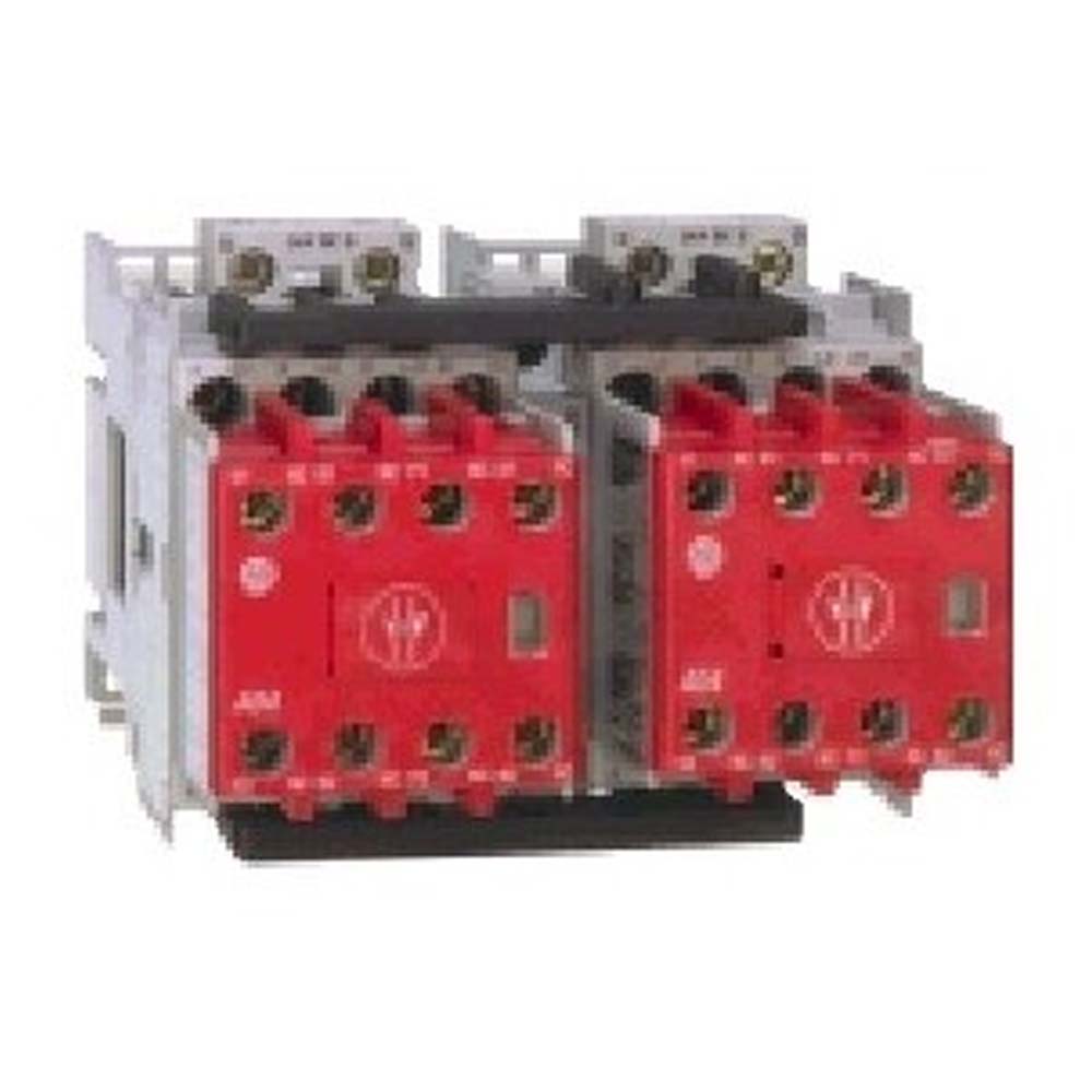
| Function | Reversing contactor |
| Rated impulse voltage withstand (Uimp) | 6 kV |
| Conventional coil type | True |
| Electronic-EI coil type | True |
| Rated coil frequency | AC 50/60 Hz, DC |
| Ripple, max | ±15% @ DC (electronic) |
| OFF time, min | 50 ms @ DC (electronic) |
| Width | 98.8 mm |
|---|---|
| Height | 80.77 mm |
| Depth | 115.62 mm |
| Auxiliary contact type | Standard contact |
| Options | No options selected |
| Optional accessories | Side-mount auxiliary contacts, surge suppressors, electronic timers, mechanical interlocks |
| Features | Positively guided/mechanically linked auxiliary contacts, front-mounted auxiliary contacts: permanently fixed, protective cover to prevent manual ops, red contact housing for easy identification, incorporates IEC 947-5-1 “Mechanically Linked” symbol |
| Recommended torque | 9 in-lb |
|---|---|
| Coil termination | Line side connection |
| Conductor cross section | Main contact, 2 conductor: 1.5...6 mm² |
| Lifespan | Mechanical DC control: 13000000 ops |
| Weight | 0.87 kg (1.91 lbs) reverse @ DC (electronic-EQ, EJ) |
| Type of electrical connection of main circuit | Screw connection |
| Auxiliary contacts | 1 NO/5 NC |
|---|---|
| Altitude of installation site, max | 2000 m (NN), per IEC60947-1 |
| Protection against accidental contact | Finger-and back-of-hand proof per VDE0106, part 100 |
| Ambient temperature | Storage: -55...80 °C (-67...176 °F) |
| Protection class, auxiliary contact | IP2X |
| Resistance to vibration | IEC 60068-2-6 |
|---|---|
| Resistance to shock | IEC 60068-2-27 |
Sales Info
| Repairable | NOT_REPAIRABLE |
| Preferred Availability | false |
| Quick Turnaround | false |
| Dimension Height | 13.335 |
| Lead Time | 54 |
| Dimension Width | 17.145 |
| Dimension Length | 23.622 |
| Weight | 1.197 |
| Weight Unit | KG |
| Dimension Unit | CM |
| 类型 | 资源 | 发布 |
|---|---|---|
| General | Short Circuit Ratings Data Sheet | -- |
| General | Repair Parts List | -- |
| General | Product Cutsheet | -- |
| Technical Data | 100-td013_-en-p | 100-TD013 |
Looking for more documentation?
Find curated technical documentation for this product in the Technical Documentation Center, or search our full Literature Library.
Search the Literature Library
- SUVA LVD Type Approval
- Korean KC
- IECEE Scheme
- UKCA DOC
- MOROCCO DOC
This product was certified with the above certifications as of 2025-06-11. Products sold before or after this date might carry different certifications. Please review the product label to check for the certifications your specific product carries.
Looking for more Technotes?
Find questions and answers from Rockwell Automation technical experts for this product in our Knowledgebase.
Search Knowledgebase
Technical Specifications
| Auxiliary Contact Cnfg | 1 NO / 5 NC |
|---|---|
| Coil Code | 24V50/60Hz/24V DC Elec Cl |
| Maximum Ampere Rating | 16 A |
| Voltage type for actuating | DC |
|---|---|
| Rated control supply voltage at AC 50 Hz | 0 V |
| Rated control supply voltage at AC 60 Hz | 0 V |
| Rated control supply voltage at DC | 24 V |
| Current (Ie), max | 16 A |
| Switching frequency, max | 220 ops/h |
| Main current circuit resistance | 2.7 mohm |
| Cross section per UL/CSA | 16 |
| Rated operational current for contactor at elevator duty (UL/CSA) | 5Hp @ 230V |
| Rated isolation voltage (Ui) | 690V @ IEC |
| Rated voltage (Ue) | 690V @ AC, 50/60 Hz |
| Rated operational power for contactor at wye-delta | 7.5Hp @ 200V, 60 Hz |
| Rated filament current | 18A @ 230/240V, AC-5b |
| Power dissipation | 2.1 W @ 400V, AC-3, Ie |
| Coil terminal conductor cross section | 1...4 mm² @ 2 conductor |
| Rated current (enclosed) | 17.5A @ 200V, 3-phase per UL/CSA |
| Rated power (enclosed) | 5Hp @ 230V, 3-phase per UL/CSA |
| Coil consumption pick-up (avg/peak) | 14/22 W @ DC (electronic-EA) |
| General purpose current (enclosed) | 30 A per UL/CSA |
| Capacitance, max | 500 µF @ short-circuit current of 20 kA |
| Switching of low inductive loads | 32A @ 440V, AC-7a per IEC 61095 (50 Hz) |
| Operating limits, pick-up | (0.85...1.1) x Us @ 50 Hz, 60 Hz, 50/60 Hz |
| Switching of motor load | 19A @ 230V, AC-7b per IEC 61095 (50 Hz) |
| Short time withstand (Icw) | 170A @ 10s, 60 °C |
| Coil consumption, hold-in | 9.5VA/2.7 W @ 50 Hz, 60 Hz, 50/60 Hz |
| Coil consumption, pick-up | 75VA @ 50 Hz, 60 Hz, 50/60 Hz |
| Operating time | 20...50 ms @ DC (electronic) opening delay |
| Total power dissipation | DC control (electronic): 3.8 W @ 400V, AC-3, Ie |
| Operating limits, dropout | (0.3...0.6) x Us @ 50 Hz, 60 Hz, 50/60 Hz |
| Switching of lamps | Gas discharge lA, open: 28A @ 40°C, AC-5a |
| Switching of hermetically sealed cooling compressor motors | 9.3A @ 690V, AC-8b (manual reset of overload release (50 Hz)) |
| Coil insulation class | Class F per IEC 60085, UL Class 105 |
| Rating for switching AC motors | 7.5 kW @ 690V @ 50Hz, 3-phase (AC-2, AC-3, AC-4) |
| BS88 fuses current rating | Type 2 (per IEC 60947-4-1): 32A @ 415V, 65 kA available fault current |
| UL class K5 and RK5 fuses rating | 70A @ 600V, 5 kA available fault current per UL 508 and CSA 22.2 No. 14 |
| UL class CC and CSA HRCI-MISC fuses rating | 30A @ 100kA available fault current per UL 508 and CSA 22.2 No. 14 |
| UL inverse-time circuit breaker | 50A @ 480V, 5 kA available fault current per UL 508 and CSA 22.2 No. 14 |
| Coil voltage | 24V DC electronic coil |
| Rated operational current (Ie) | 9A @ 690V, AC-4 (approximately 200000 ops) |
| Rated operational power (Pe) | 7.5 kW @ 690V, AC-4 (approximately 200000 ops) |
| DIN fuses (gG, gL) current rating | Type 2 (per IEC 60947-4-1): 35A @ 690V, 50 kA available fault current |
| UL class J and CSA HRCI-J fuses rating | 30A @ 100kA available fault current per UL 508 and CSA 22.2 No. 14 |
| Switching of power transformers | Apparent power: 9.4 kVA @ 500V, AC-6a @ 50Hz (n = 30) |
| Switching of 3-phase Capacitors | Single capacitor: 8.5 kVAR @ 240V, AC-6b, 50 Hz, 60 °C (inductance of leads between capacitors in parallel: minimum 6 µH) |
| Switching of DC loads | 3-pole:32A @ 110V (Non-inductive or slightly inductive loads or resistance furnaces DC-1 at 60 °C) |
| Contacts | 3 main poles with NC mechanically linked or mirror ftdback contacts |
| Function | Reversing contactor |
| Rated impulse voltage withstand (Uimp) | 6 kV |
| Conventional coil type | True |
| Electronic-EI coil type | True |
| Rated coil frequency | AC 50/60 Hz, DC |
| Ripple, max | ±15% @ DC (electronic) |
| OFF time, min | 50 ms @ DC (electronic) |
| Width | 98.8 mm |
|---|---|
| Height | 80.77 mm |
| Depth | 115.62 mm |
| Auxiliary contact type | Standard contact |
| Options | No options selected |
| Optional accessories | Side-mount auxiliary contacts, surge suppressors, electronic timers, mechanical interlocks |
| Features | Positively guided/mechanically linked auxiliary contacts, front-mounted auxiliary contacts: permanently fixed, protective cover to prevent manual ops, red contact housing for easy identification, incorporates IEC 947-5-1 “Mechanically Linked” symbol |
| Recommended torque | 9 in-lb |
|---|---|
| Coil termination | Line side connection |
| Conductor cross section | Main contact, 2 conductor: 1.5...6 mm² |
| Lifespan | Mechanical DC control: 13000000 ops |
| Weight | 0.87 kg (1.91 lbs) reverse @ DC (electronic-EQ, EJ) |
| Type of electrical connection of main circuit | Screw connection |
| Auxiliary contacts | 1 NO/5 NC |
|---|---|
| Altitude of installation site, max | 2000 m (NN), per IEC60947-1 |
| Protection against accidental contact | Finger-and back-of-hand proof per VDE0106, part 100 |
| Ambient temperature | Storage: -55...80 °C (-67...176 °F) |
| Protection class, auxiliary contact | IP2X |
| Resistance to vibration | IEC 60068-2-6 |
|---|---|
| Resistance to shock | IEC 60068-2-27 |
Sales Info
| Repairable | NOT_REPAIRABLE |
| Preferred Availability | false |
| Quick Turnaround | false |
| Dimension Height | 13.335 |
| Lead Time | 54 |
| Dimension Width | 17.145 |
| Dimension Length | 23.622 |
| Weight | 1.197 |
| Weight Unit | KG |
| Dimension Unit | CM |
文档
|
Short Circuit Ratings Data Sheet
General
-- |
|
Repair Parts List
General
-- |
|
Product Cutsheet
General
-- |
|
100-td013_-en-p
Technical Data
100-TD013 |
| 类型 | 资源 | 发布 |
|---|---|---|
| General | Short Circuit Ratings Data Sheet | -- |
| General | Repair Parts List | -- |
| General | Product Cutsheet | -- |
| Technical Data | 100-td013_-en-p | 100-TD013 |
Looking for more documentation?
Find curated technical documentation for this product in the Technical Documentation Center, or search our full Literature Library.
Search the Literature Library
认证
- SUVA LVD Type Approval
- Korean KC
- IECEE Scheme
- UKCA DOC
- MOROCCO DOC
This product was certified with the above certifications as of 2025-06-11. Products sold before or after this date might carry different certifications. Please review the product label to check for the certifications your specific product carries.
Alternative Products
Technotes
Looking for more Technotes?
Find questions and answers from Rockwell Automation technical experts for this product in our Knowledgebase.
Search Knowledgebase
Loading
Copyright ©2025 Rockwell Automation, Inc.